


Views: 0 Author: Site Editor Publish Time: 2026-09-09 Origin: Site


Hidden operational costs of check valve failure threaten oil pipelines daily. Unplanned downtime halts production schedules, while severe pressure loss destabilizes entire fluid networks. Catastrophic environmental hazards often follow sudden containment breaches. Many operators fall for the "install and forget" fallacy, treating these components as passive and maintenance-free. This underrated mindset causes preventable pipeline failures. Misapplication of valve types drives these issues. Wrong installation orientation ruins internal mechanisms. Poor flow dynamics cause severe internal chatter, and improper thread sealing leads to dangerous external leaks. These errors cause premature internal wear and system-wide instability. We need a technical, evidence-based framework. You must evaluate, specify, install, and maintain these components properly. This approach ensures long-term pipeline integrity and safety.
Orientation Dictates Design: Vertical mounting requires specific internal mechanisms (e.g., spring-assisted or axial flow) to prevent gravity-induced failure and dangerous backflow.
Precision in Installation: Threaded connections demand exact sealant application, flow-direction verification, and torque specifications to mitigate high-pressure hydrocarbon leakage and thread galling.
Proactive Diagnostics: Routine check valve maintenance, utilizing acoustic monitoring and targeted seal lubrication, extends lifecycle and prevents sudden catastrophic failure.
Flow-Matched Sizing & Piping Design: Proper valve sizing and adequate straight pipe runs are critical to maintaining consistent line pressure and eliminating destructive water hammer (valve slam) and turbulence.
System stability relies on consistent fluid control. Check valves maintain steady line pressure across complex piping networks by allowing hydrocarbon flow in only one direction. This unidirectional control prevents dangerous pressure surges that can tear apart manifolds. Reverse flow disrupts upstream processes immediately. A properly specified threaded check valve stops this reversal instantly. It isolates different pressure zones effectively. Stable operation requires immediate valve closure upon pump shutdown. Delayed closure allows the fluid column to reverse, accelerating the fluid mass backward. The resulting kinetic energy damages pipeline infrastructure and blows out flange gaskets.
Asset protection remains a primary engineering objective in any facility. High-value upstream equipment requires shielding from mechanical shock. Centrifugal pumps suffer severe impeller damage and shaft deflection from reverse rotation. Compressors sustain catastrophic dry-gas seal failures during backflow events. Positive displacement flow meters lose calibration accuracy when subjected to reverse surges. Check valves act as the primary defense mechanism against these events. They absorb the hydraulic shock before it reaches sensitive machinery. Fast-acting closure mechanisms prevent the fluid from gaining backward momentum. This rapid response protects capital investments from sudden destruction.
Application suitability dictates connection types across the site. Threaded connections serve specific pipe diameters efficiently. Engineers specify NPT or BSPT threads for lines under four inches. These connections handle high pressure classes reliably without the massive footprint of flanged joints. They offer a compact profile for tight installation spaces on chemical injection skids and metering runs. Threaded joints eliminate the bulky profile of flanged alternatives, making them easier to insulate and trace. They provide a secure, leak-resistant seal when assembled correctly. Proper thread engagement ensures structural integrity under heavy vibration from nearby reciprocating pumps.
Different valve designs serve distinct operational requirements, and picking the wrong one guarantees failure. Swing check valves offer high flow capacity and create a very low pressure drop across the seat. A hinged disc swings open under forward flow. However, they possess severe limitations in vertical orientations. Gravity pulls the disc downward asynchronously with fluid deceleration. This delay causes violent valve slam upon closure. The hinge pin wears oval over time, causing the disc to hang up and fail to seat properly.
Lift check valves perform well in high-pressure gas applications where tight shutoff is required. A piston or ball lifts off the seat vertically. Unfortunately, they remain highly susceptible to particulate jamming in liquid service. Unrefined crude oil streams contain sand, scale, and debris. These particulates wedge between the piston and the guide wall, causing the internal mechanism to stick wide open. Once a lift check sticks open, it offers zero backflow protection.
In-line spring-assisted valves provide the optimal solution for most liquid hydrocarbon lines. They mitigate water hammer effectively across all orientations. An internal spring forces the disc closed rapidly as forward velocity drops. This closure happens before the fluid actually reverses direction. The design offers versatile mounting options for complex piping layouts. They close silently and prevent hydraulic shock waves from traveling through the pipe network.
Valve Design | Flow Capacity | Vertical Mount Suitability | Primary Failure Mechanism in Crude Oil | Water Hammer Prevention |
|---|---|---|---|---|
Swing Check | High | Poor (Prone to severe slam) | Hinge pin wear from flow turbulence | Low |
Lift Check | Medium | Fair (Upward flow only) | Particulate jamming in the piston guide | Moderate |
Spring-Assisted | Medium-High | Excellent | Spring fatigue over extended lifecycles | High |
Metallurgical compatibility determines operational lifespan in the field. Carbon steel (like ASTM A105) offers robust strength for standard oil environments. It handles high pressure but lacks severe corrosion resistance against internal moisture. Stainless steel (such as 316L) provides superior protection against internal degradation and pitting. Specialized alloys become necessary for aggressive fluid profiles. Sour gas environments contain high levels of hydrogen sulfide, which attacks standard steel rapidly through sulfide stress cracking.
Engineers must select NACE MR0175 compliant materials for these sour conditions. Duplex stainless steels resist chloride stress corrosion cracking in offshore applications. Proper material selection prevents sudden pressure boundary failures. You must match the metallurgy to the specific crude composition. A reliable thread check valve depends entirely on its base material holding up to the chemical attack of the fluid.
Regulatory standards ensure structural integrity and safe operation. API 594 dictates design requirements for check valves, covering pressure-temperature ratings and minimum wall thickness. API 6D specifies testing protocols for pipeline valves to ensure seat tightness. ASME B16.34 governs the construction of threaded end connections and body casting quality. Strict compliance guarantees the valve withstands pipeline stresses without rupturing. Manufacturers must provide material test reports (MTRs) for verification. These documents trace the chemical composition of the cast body back to the foundry. Ignoring these standards invites catastrophic pipeline ruptures.
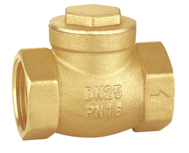
Straight pipe runs remain an absolute engineering necessity for check valve longevity. You must maintain three to five pipe diameters of straight run upstream and downstream of the installation point. Elbows, tees, and reducers create severe fluid turbulence. Placing a valve too close to these fittings disrupts the velocity profile. The turbulent flow strikes the valve disc unevenly, causing rapid internal chatter. The disc bounces violently against the seat dozens of times per second. Premature internal wear destroys the sealing surfaces quickly under these conditions. Proper spacing allows the fluid velocity profile to stabilize, keeping the disc fully open and stationary.
Pre-installation flow verification prevents immediate system failure upon startup. Every check valve features a directional flow arrow cast directly onto the valve body. You must verify this arrow aligns with the intended fluid direction. Installing the valve backward blocks the line completely. The pump will dead-head against the closed disc, causing immediate and severe pump damage. Pressure builds rapidly until a mechanical seal blows or a pipe ruptures. Field technicians must double-check this orientation before applying thread sealant. Visual confirmation takes seconds but saves entire pipeline sections from overpressurization.
Flow direction dynamics change drastically in vertical piping systems. Upward flow fights gravity constantly, requiring higher pump head pressure. Downward flow works with gravity but risks siphoning and column separation. Vertical upward flow requires specific valve mechanics to function safely. The fluid must lift the disc against its own weight and hold it there. When the pump stops, the fluid column drops instantly. Standard swing check valves routinely fail in this orientation because the hinge mechanism relies on fluid velocity to stay open.
Gravity pulls the heavy disc down as flow slows, but the fluid reverses faster than the disc swings shut. The reversing fluid catches the disc and slams it into the seat with massive force. This gravity problem destroys piping infrastructure. The violent slam sends a shockwave through the system, breaking pipe supports under the sudden stress. Threaded joints loosen and begin leaking hydrocarbons. Balancing gravity against flow velocity proves impossible with swing designs. You must address these physics during the initial design phase to avoid guaranteed mechanical failure.
Mechanical assistance solves the vertical installation problem entirely. You must specify spring-loaded or axial flow designs for these runs. A vertical mount check valve relies on internal spring force to control the disc. This spring pushes the disc toward the seat continuously. As forward flow decreases, the spring takes over and forces the disc closed at zero flow. This happens prior to any fluid reversal. The mechanical assist eliminates the reliance on gravity and guarantees instantaneous closure regardless of orientation. This design prevents the destructive hydraulic shock entirely.
Cracking pressure calculations ensure proper system function and pump efficiency. Cracking pressure is the minimum upstream pressure required to push the disc off the seat. You must calculate this value accurately for vertical runs. The fluid must overcome the internal spring force and the static head of the vertical oil column. If the cracking pressure is too high, flow restricts severely, and the pump consumes excess energy. If it is too low, the valve may chatter at low flow rates. Engineers must match the spring rate to the specific pump curve to ensure smooth opening and tight closing.
External leakage stems from improper installation techniques and harsh environmental factors. Thread galling occurs frequently during assembly of stainless steel components. The threads fuse together under high friction, creating a cold-weld that prevents proper tightening. Improper torque application distorts the valve body permanently. Excessive force warps the internal seating surfaces, while insufficient torque leaves microscopic gaps in the thread root. Thermal cycling exacerbates these issues in exposed pipelines. Sun exposure heats the metal, causing expansion, while cold nights cause rapid contraction. This constant movement loosens threaded connections over time, allowing hydrocarbons to find pathways into the environment.
Internal leakage, known as passing, degrades system efficiency and compromises isolation. Seat wear results from continuous particulate abrasion in unrefined streams. Sand in the crude oil acts like sandpaper, scoring the metal seating surfaces deeply over months of operation. Improper seating also causes internal passing. Chronic low-flow conditions prevent the disc from opening fully. The disc hovers near the seat, chattering constantly. This repeated impact deforms the precision-machined seal. Once the seat deforms, reverse flow slips past the barrier. Passing valves fail to hold pressure during pump shutdowns, bleeding high-pressure fluid back into low-pressure headers.
Sealant specification requires strict attention to detail to ensure a hermetic seal. You must select the correct thread sealant for the specific fluid. High-density PTFE tape works well for industrial applications, but it must be explicitly rated for hydrocarbons. Standard plumbing tape dissolves in crude oil, leaving the joint unprotected. Liquid thread sealants provide an excellent alternative for high-vibration areas. They fill the microscopic spiral leak paths between the male and female threads. These compounds cure into a hard, solvent-resistant plastic that prevents galling while ensuring a tight seal. Always apply sealants according to manufacturer guidelines, as over-application pushes debris into the pipeline.
Wire brush the male pipe threads thoroughly to remove rust, dirt, and old sealant.
Apply a hydrocarbon-rated liquid thread sealant to the first three leading threads.
Wrap high-density, gas-rated PTFE tape clockwise around the threads, overlapping each wrap by fifty percent.
Thread the valve onto the pipe by hand until you feel firm mechanical resistance.
Apply a calibrated torque wrench to the hex end of the valve closest to the pipe engagement to prevent body distortion.
Remedial sealing addresses minor internal leaks temporarily to keep the unit online. You can address passing through targeted injection if the valve design allows it. Some larger threaded valves feature standard seat injection ports. Technicians inject light-grade lubricants or specialized synthetic total-lube sealants into these ports. The heavy sealant fills the microscopic scratches on the metal seat, restoring the seal temporarily without requiring a pipeline shutdown. It buys time until the next scheduled maintenance window. This method works only for minor abrasive wear. Severe mechanical damage requires complete valve replacement.
Installation protocols prevent mechanical distortion and ensure long-term reliability. Implement strict, documented torque guidelines for all field crews. Technicians must use calibrated torque wrenches and never rely on physical feel alone. Secure the valve body properly during installation. Twisting from the opposite end of the valve twists the body, ruining the internal seat alignment. Document the final torque values for maintenance records to track installation quality. A properly installed oil pipeline check valve will operate leak-free for years.
Frequency baselines replace reactive emergency repairs with predictable operational expenses. You must establish inspection intervals based on actual operating conditions rather than arbitrary calendar dates. Fluid corrosivity dictates how often you inspect the internals for pitting. High flow rates accelerate mechanical wear on the hinge pins and springs. Operating pressures determine the stress on the pressure boundary. Historical cycle counts provide the best wear indicator. A valve cycling ten times daily wears faster than one cycling monthly. Schedule visual inspections of threaded joints quarterly to check for weeping oil or accumulated dirt around the threads. Proactive check valve maintenance prevents catastrophic environmental spills.
Non-Destructive Testing (NDT) keeps pipelines running during critical inspections. Acoustic emission testing detects internal passing accurately without breaking containment. Technicians attach sensors to the valve body externally and listen for the high-frequency hiss of leaking fluid. This acoustic signature occurs when the valve is supposed to be fully closed but fluid is slipping past the scored seat. Ultrasonic monitoring measures wall thickness degradation, detecting internal corrosion without opening the pipe. These NDT methods require zero pipeline downtime and provide actionable data on internal seat condition. Schedule acoustic testing annually for critical isolation points.
Resolving valve chatter requires immediate flow analysis. Chatter indicates an oversized valve for the current flow rate. The fluid velocity cannot hold the disc fully open, causing it to bounce on the fluid stream. Identify these oversized units through vibration analysis and replace them with properly sized valves. A smaller valve requires higher velocity to pass the same volume, which pins the disc firmly against the open stop. This eliminates the hinge-pin wear entirely. Correct sizing ensures stable, quiet operation and extends the lifecycle of the internal components.
Eliminating water hammer protects the entire facility from structural damage. Water hammer sounds like a physical hammer striking the pipe and occurs when a swing valve closes too late. The reversing fluid slams the disc shut violently, sending a pressure spike through the system. Transition away from standard swing designs immediately if you hear this noise. Install non-slam, spring-assisted valves instead. The spring absorbs the hydraulic shock and forces the disc closed before the fluid accelerates backward. Upgrading a single problematic valve can stabilize an entire pumping station.
Audit your current piping isometric drawings to identify and replace any standard swing check valves currently installed in vertical upward flow lines.
Standardize your installation protocols by mandating the use of calibrated torque wrenches and hydrocarbon-rated, high-density PTFE sealants on all threaded connections.
Implement an annual acoustic emission testing schedule for all critical isolation valves to detect internal passing before severe pressure loss occurs.
Recalculate cracking pressure requirements against your current pump curves to ensure all spring-assisted valves are properly sized for actual field flow rates.
A: Standard swing valves often fail vertically. Gravity pulls the disc down, but fluid reverses faster than it closes, causing violent slam. A specialized vertical mount check valve with a spring-assist is required for upward flow. The spring forces instantaneous closure before reverse flow begins.
A: External leaks stem from thread deformation, improper installation torque, and thermal cycling. Internal leaks occur due to seat wear from abrasive crude oil particulates. Chronic low-flow conditions also cause valve chatter, which permanently deforms the precision-machined internal seating surfaces.
A: Follow API-recommended intervals based on fluid corrosivity and cycle counts. Visual inspections for external thread leaks should occur quarterly. Acoustic testing for internal passing should be performed annually or bi-annually, depending on the valve's operational frequency and criticality.
A: NPT (National Pipe Taper) and BSPT (British Standard Pipe Taper) have different thread angles and pitch configurations. NPT threads have a 60-degree angle, while BSPT uses a 55-degree angle. They are physically incompatible. Mixing them guarantees severe hydrocarbon leakage and thread damage.
A: You must transition to non-slam, spring-loaded designs. Valve slam occurs when reverse flow accelerates the disc into the seat. A spring-assisted valve pushes the disc closed at zero flow, shutting completely before the fluid can reverse direction and generate hydraulic shock.
A: Yes, but only temporarily. You can inject specialized synthetic lubricants into standard seat injection ports. This total-lube sealant fills microscopic scratches caused by abrasive wear. It serves as a temporary mitigation strategy to maintain pressure until a scheduled maintenance shutdown allows for replacement.


