


Views: 0 Author: Site Editor Publish Time: 2026-08-31 Origin: Site


Installing flow control devices in tight pump rooms or high-density municipal facilities requires highly specific engineering approaches. Severe space limitations often force system designers to seek out components boasting minimal face-to-face dimensions. You cannot easily fit standard, bulky gate structures into these restricted footprints.
While the wafer design successfully saves critical pipeline space, its unique structure completely lacks threaded lugs. It relies entirely on the precise clamping force of adjacent pipe flanges to stay perfectly secure. Improper physical alignment or incorrect bolting torque frequently leads to uneven elastomeric seat compression. This quickly causes internal disc interference and eventual joint leakage.
This comprehensive guide provides a technically sound, standard-compliant framework for handling these specific operational challenges. We will clearly walk you through preparing, installing, and evaluating these specific wafer-style components. You will discover actionable, practical strategies to ensure long-term mechanical reliability across all your compact water networks.
Proper disc clearance verification prior to tightening is critical to prevent disc edge damage against internal pipe walls.
A wafer butterfly valve requires precise centering between flanges; unlike lug valves, it cannot be used for dead-end service or downstream line removal.
Adhering to a star-pattern (cross-pattern) torquing sequence prevents uneven compression of the elastomeric seat, which acts as the primary flange seal.
Evaluating supplier compliance with AWWA or ISO standards ensures the water system butterfly valve withstands the specific pressure ratings of municipal and commercial pump environments.
Pump room retrofits and skid-mounted water systems severely limit available pipeline real estate. Engineers must optimize every single inch of face-to-face dimensions during the design phase. Crowded facilities leave very little room for bulky equipment or extensive maintenance clearances. This business problem forces facility managers to rethink standard piping layouts entirely. You must find ways to reduce the overall mechanical footprint without sacrificing pressure isolation capabilities.
The wafer style serves as a highly efficient compact butterfly valve in these tight scenarios. It significantly reduces the overall weight placed on your piping infrastructure. It also minimizes the structural load pulling on pipe hangers, especially when compared to fully flanged or heavy lug alternatives. Its minimalist, ring-like body easily slides between standard flanges. This streamlined approach makes it exceptionally popular for densely packed municipal pump stations.
However, you must clearly understand the limitations and assumptions surrounding this selection. Evaluation criteria strictly dictate where you can safely deploy these units. First, evaluate their isolation capabilities. They strictly require flanges on both sides to hold system pressure effectively. You cannot safely use them for end-of-line service. Second, consider the maintenance impact. Removing one requires completely draining the entire line segment. Lug styles, conversely, allow you to disconnect downstream piping while keeping the upstream section pressurized. You should specify the wafer style strictly for in-line control applications. Use it only where weight reduction and space savings clearly outweigh the need for single-side pipe maintenance.
The comparison chart below highlights the primary functional differences to guide your selection process.
Functional Feature | Wafer Style | Lug Style |
|---|---|---|
Body Design | Minimalist ring body without threaded inserts | Features threaded metal inserts surrounding the body |
Space & Weight Efficiency | Maximum space savings, lowest overall weight | Heavier, requires slightly more physical clearance |
End-of-Line Suitability | Not suitable (requires dual flange compression) | Highly suitable (can hold pressure unilaterally) |
Maintenance Flexibility | Requires draining the entire piping section | Allows safe downstream pipe removal |
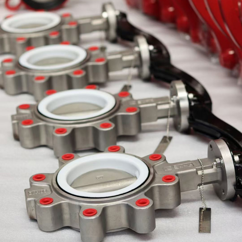
Thorough preparation prevents catastrophic mechanical failures down the line. You must conduct rigorous pre-installation checks before moving any equipment into the pump room. Rushing this stage often results in torn seats, bent discs, or severe joint leaks.
Verify the internal diameter of the adjacent piping immediately. Pay exceptionally close attention to thick-walled pipes, such as Schedule 80 carbon steel. Thick pipe walls often drastically reduce the internal clearance. The outer edge of the disc travels in a specific swing chord when opening. If the pipe wall is too thick, it will inevitably obstruct the disc. This interference causes severe mechanical damage to the disc edge. It also stresses the actuator and ruins the sealing mechanism. You must confirm that your specific pipe schedule accommodates the full swing of the disc without any contact.
Understanding flange dynamics is critical for a leak-free setup. Common mistakes here ruin the elastomeric seal.
No Separate Gaskets Needed: These specific designs generally do not require separate flange gaskets. The integral elastomeric seat extends slightly past the metal body. This protruding rubber liner forms the primary seal against the mating pipe flanges. Adding standard drop-in gaskets causes severe over-compression. It distorts the rubber and inevitably leads to unpredictable joint leaks.
Welding Precautions: You must ensure all weld-neck or slip-on flanges are fully welded before starting the installation. Allow the hot metal flanges to cool completely to ambient room temperature. Inserting the unit between hot flanges transfers extreme heat directly to the delicate rubber seat, melting or permanently hardening the elastomer.
Surface Finish: Inspect the flange faces for deep scratches, weld spatter, or leftover rust. The flange faces must remain smooth and clean to achieve a perfect seal against the rubber liner.
Municipal water applications demand strict adherence to recognized engineering standards. You must verify that your chosen component fully meets AWWA C504 or equivalent international benchmarks. This verification ensures proper water contact safety. It also guarantees reliable coating integrity, robust shaft dimensions, and rigorous hydrostatic pressure testing. Installing non-compliant hardware in public water networks introduces massive operational risks.
Executing a flawless installation requires patience, precision, and adherence to specific mechanical steps. Following this exact sequence protects the soft elastomer seat from tearing while ensuring perfectly parallel flange mating.
Step 1: Pipeline Preparation & Spacing
Begin by spreading the mating flanges apart using appropriate mechanical tools or flange spreaders. You must create enough physical clearance so the body slides in smoothly. Never force the unit into a tight gap. Forcing it will drag the protruding rubber seat against the rough metal flanges, instantly tearing the seal before the system ever goes live.
Step 2: Valve Positioning
Insert the unit with the internal disc resting in a partially open position. You should aim for an angle between 10° and 15°. This specific angle is a crucial expert practice. Fully closed discs exert excessive outward pressure on the rubber seat. Tightening the flanges while fully closed permanently distorts the elastomer. Conversely, a fully open disc exposes the delicate outer edges, risking severe damage if they strike the heavy pipe flanges during insertion.
Step 3: Centering & Bolt Insertion
Pass the bottom bolts through the lower flange holes first. This action creates a supportive mechanical cradle. Carefully lower the unit into this cradle. You must ensure absolute concentricity with the pipeline. Perfect centering guarantees uniform sealing pressure across the entire circumference of the joint. If you mount it off-center, one side will crush the rubber while the other side barely touches it, guaranteeing a leak.
Step 4: Initial Hand-Tightening & Disc Clearance Check
Insert all remaining bolts through the flange holes. Thread the nuts on, but only hand-tighten them at this stage. Do not apply a wrench yet. Before proceeding, cycle the handle slowly to the fully open position. You must visually and physically verify the disc completely clears the adjacent pipe interior. It must swing freely without binding or scraping the pipe ID. Once verified, return the disc to the slightly open 10° position.
Step 5: Staged Torquing Sequence
Apply final torque using a strictly defined star (cross) pattern. You must tighten the bolts in three distinct, progressive stages. We recommend applying 30% of the specified torque first, moving across the star pattern. Then increase to 60%, and finally finish at 100% of the manufacturer’s specified torque limit. This staged method ensures completely parallel flange mating. It prevents uneven crushing of the seat and keeps the internal shaft perfectly aligned.
Even with careful preparation, mechanical systems occasionally present unexpected challenges upon startup. Recognizing the root causes of common failures allows field technicians to resolve issues quickly. You must address these risks immediately to protect the infrastructure.
Flange leaks represent the most common post-installation headache. This failure typically stems from uneven bolting torque. If a technician tightens one side completely before moving to the other, the rubber seat crushes unevenly. Another frequent cause is the unauthorized use of additional flat gaskets. Misaligned or off-center flanges also create severe leak paths. If you spot a leak, depressurize the system immediately. Never attempt to tighten bolts on a fully pressurized line. Loosen the hardware, re-center the body carefully, and re-torque everything using the strict staged star sequence.
Sometimes the actuator struggles to turn the shaft, or a manual handle feels completely jammed. This binding usually happens because over-torqued flange bolts compress the seat too tightly against the disc edge. Alternatively, the disc might be physically interfering with a thick pipe ID. You must verify your pipe schedule compatibility again. Check the manufacturer’s specific torque limits for the flange bolts. Remember a crucial rule: over-tightening the bolts does not improve the seal. It only distorts the rubber and rapidly degrades the seat lifecycle.
Many technicians mistakenly believe all wafer styles are completely bi-directional without exception. While mostly bi-directional, some high-performance or specific offset designs feature a preferred flow direction. These specialized units seal much more effectively when fluid pressure hits a specific side of the disc. Always inspect the external body casting closely. Look for a cast directional arrow. Following this orientation ensures optimal seating pressure and promotes a significantly prolonged lifecycle for the internal components.
Procuring reliable hardware matters just as much as flawless installation. Critical water infrastructure demands components that withstand decades of continuous use. You must evaluate potential suppliers based on strict technical criteria rather than simply choosing the lowest bid.
Ensure your chosen supplier provides clear, documented Bills of Materials (BOM) for every unit. You need absolute certainty regarding the internal wetted parts. Look specifically for appropriate seat materials like EPDM or NBR, which handle municipal water safely. Evaluate the disc materials thoroughly. Demand components made from robust Ductile Iron, Stainless Steel, or those featuring specialized anti-corrosion coatings like Nylon or Epoxy. Poor material choices inevitably lead to rapid corrosion and total system failure.
Look for vendors who explicitly state their face-to-face manufacturing standards. They should prominently display compliance with recognized benchmarks like API 609 or EN 558. Adhering to these strict dimensional standards ensures seamless drop-in replacement compatibility. When a maintenance team needs to swap a unit twenty years from now, standardized dimensions guarantee the new part will fit perfectly between the existing flanges without requiring expensive pipe modifications.
Prioritize suppliers offering highly accessible, well-written Operation and Maintenance (O&M) manuals. Request clear engineering drawings and flow coefficient charts up front. Furthermore, ensure they provide responsive, highly competent technical engineering support. Complex municipal installations often present unique hydraulic challenges. Having direct access to factory engineers proves invaluable when you need to verify actuator sizing, custom torque requirements, or specific pressure drop calculations.
Correct installation of a wafer butterfly valve remains a strict exercise in mechanical precision. By respecting proper flange spacing, ensuring absolute centering, and following rigorous torquing protocols, facilities can vastly maximize the lifespan of these vital space-saving components. Ignoring these fundamentals inevitably leads to torn seals, jammed discs, and costly facility downtime.
Verify pipe internal dimensions carefully to prevent destructive disc interference.
Never use additional gaskets; rely entirely on the integral elastomeric seat.
Always torque flange bolts progressively using a strict cross pattern.
Never install this specific design at the end of a pressurized pipeline.
Review your upcoming project pipe schedules and system pressure requirements against manufacturer specifications before finalizing any procurement. Contact a certified engineering or technical sales representative today. They will help verify material suitability and dimensional compatibility for your specific municipal water system parameters, ensuring a seamless, leak-free deployment.
A: In most cases, no. The rubber seat of a resilient-seated valve acts directly as the flange gasket. Adding secondary flat gaskets can cause severe uneven compression. This distortion ultimately leads to unpredictable and stubborn joint leaks.
A: No. Because wafer valves rely entirely on the mechanical compression between two opposing pipe flanges to maintain their position and secure the seal, they cannot safely isolate a dead-end line. A lug-style valve is strictly required for end-of-line service.
A: Always verify the internal diameter of your adjacent piping against the valve disc's specific swing chord. This is especially critical for heavy-wall Schedule 80 pipes. Open the valve manually to check clearances before finalizing any flange bolt torque.
A: Standard resilient-seated wafer valves operate bi-directionally. However, high-performance or specific offset butterfly valves may feature a preferred flow direction. This is usually indicated by a prominent arrow cast directly on the valve body. Always consult the manufacturer's technical manual to be certain.


