


Views: 0 Author: Site Editor Publish Time: 2026-08-24 Origin: Site


Specifying the wrong industrial valve leads to disastrous results. You risk either premature catastrophic failure from under-specifying or wasted capital expenditure from over-specifying. Industrial piping systems demand exact precision. Engineers often look at visual similarities and assume equal performance. While both types control flow using a simple quarter-turn disc, they differ fundamentally inside. Their internal geometry, specific seating mechanisms, and pressure limits dictate entirely different use cases. Choosing incorrectly compromises system safety. This guide strips away confusing marketing claims. We provide a purely technical and commercial evaluation framework. Procurement teams and process engineers can use this operational data. You will learn how to properly match the exact valve architecture to your unique system requirements.
Geometry dictates limits: Standard wafer butterfly valves utilize a concentric design with elastomeric seats (ideal for low-pressure, ambient utilities), whereas a high performance butterfly valve uses a double or triple offset design to handle extreme conditions.
Terminology clarification: "Wafer" refers to the body connection style (clamped between flanges), but "standard wafer" colloquially refers to resilient-seated, concentric utility valves. High-performance valves can also feature wafer-style bodies.
Cost vs. Risk: Standard resilient-seated valves offer massive upfront CAPEX savings; high-performance valves justify their higher cost through extended lifecycle (OPEX) in abrasive, high-temperature, or high-cycle environments.
You cannot judge an industrial valve by its exterior housing. The true capabilities lie within the internal geometry. Engineers group these valves based on where the stem positions the disc relative to the seat. We must examine concentric designs and offset engineering to understand their structural limits.
A standard concentric design offers simplicity. Manufacturers build these valves for general utility service. They dominate basic water and air applications.
Mechanics: The stem runs directly through the center of the disc. The disc sits perfectly in the center of the valve bore. This symmetrical design creates a balanced flow path.
Seating: This architecture relies entirely on an interference fit. The metal disc maintains constant physical contact against a rubber or elastomer seat. Common seat materials include EPDM, Buna-N, and NBR. The seat physically deforms around the disc edge to create a tight seal.
Wear Profile: This constant friction comes with a significant drawback. The continuous scraping action leads to faster seat degradation. High-cycle operations destroy resilient seats quickly. You will see performance drop rapidly if you actuate them hundreds of times a day.
Many engineers default to this design. It works well for benign conditions. However, you must recognize its mechanical boundaries before installation.
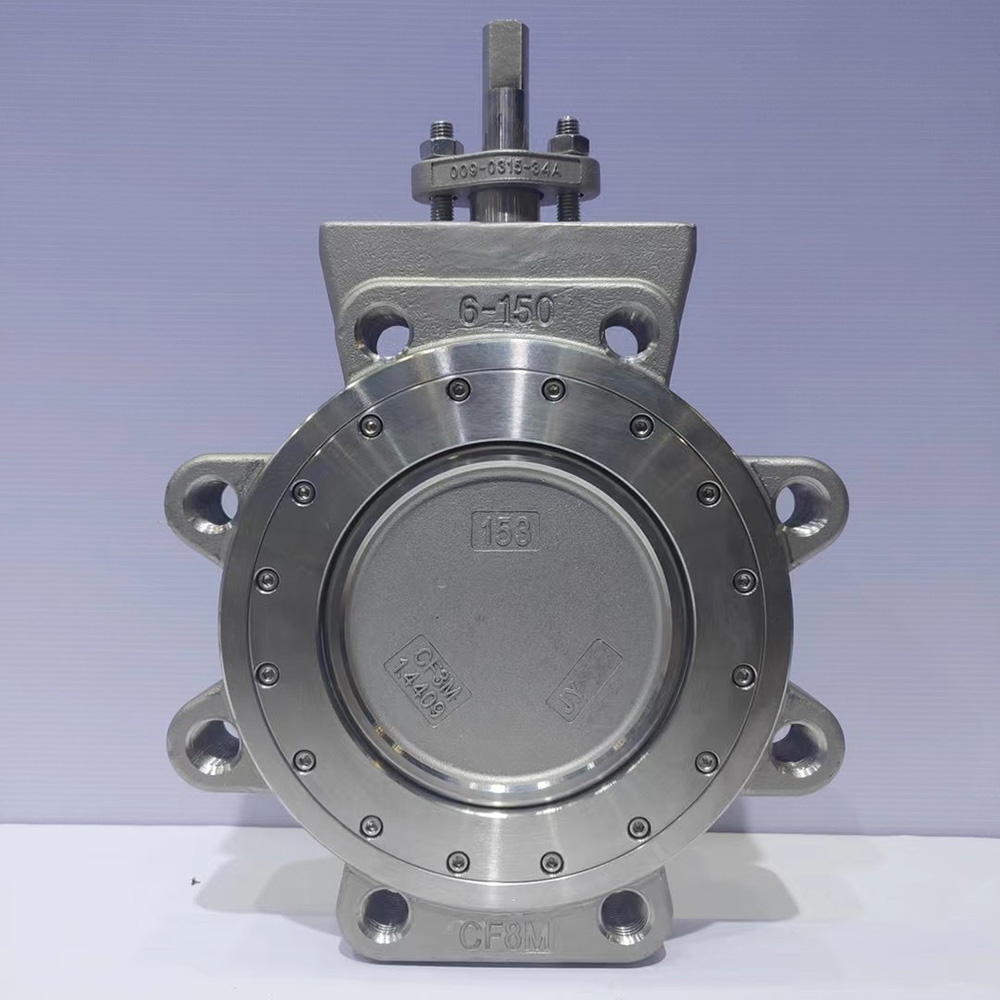
Demanding industrial applications require advanced geometry. Engineers cannot rely on simple rubber deformation for critical processes. A high performance butterfly valve solves the friction problem through offset mechanics. It separates the sealing function from constant physical scraping.
Mechanics: The stem sits behind the center of the disc. It also sits slightly off to one side of the pipe centerline. This double offset creates a unique rotation path. Triple offset designs add a conical seat angle for even more precision.
Seating: This offset geometry generates a specific cam-action operation. The disc pulls away from the seat immediately upon opening. It only contacts the seat during the final degrees of closure. This drastically reduces internal friction. It eliminates the constant scraping seen in concentric designs.
Seat Materials: Because the design minimizes friction, manufacturers can use rigid seating materials. They utilize engineered polymers like PTFE or RTFE. For severe services, they employ solid metal-to-metal seats. These rigid materials survive where elastomers melt or shatter.
Internal geometry directly dictates operational limits. You must align your system conditions with the correct valve architecture. Pushing a basic valve beyond its design parameters guarantees failure. We evaluate these limits across three specific engineering metrics.
Pressure causes physical stress on the disc and stem. Valve bodies must contain this internal energy safely.
A standard utility valve handles modest pressures. Manufacturers typically limit them to ANSI Class 150 specifications. In real-world terms, this means a maximum operating pressure of roughly 150 to 250 PSI. The exact limit depends on the valve diameter and the manufacturer. They work perfectly for municipal water lines or HVAC chilled water loops.
High-performance designs withstand massive internal forces. Engineers routinely specify them for Class 150, Class 300, and Class 600 applications. They easily handle system pressures reaching 1440 PSI or higher. The robust stem sizing and rigid seat retention allow them to block high-energy fluid streams without bending.
Thermal energy destroys incorrect seating materials. Temperature thresholds often dictate your final valve selection.
Standard resilient valves face severe thermal constraints. You are bound by the chemical limits of elastomers. EPDM and Buna-N rubber rarely survive continuous exposure above 250°F (120°C). They harden, crack, and fail rapidly in steam service. You should never specify a rubber-seated valve for steam lines.
Offset valves excel in extreme thermal environments. PTFE polymer seats comfortably handle continuous temperatures up to 400°F (204°C). When you upgrade to metal seats, the limits jump drastically. Metal-seated variants withstand superheated conditions exceeding 1000°F (538°C). They also handle deep cryogenic services down to -320°F (-196°C). You need this resilience for liquid nitrogen or high-pressure steam processing.
Chemical attack ruins piping infrastructure. You must match the seat material to the fluid chemistry.
Standard rubber seats show extreme vulnerability to harsh chemicals. Hydrocarbons, acids, and aggressive solvents dissolve NBR and EPDM. A swollen rubber seat jams the disc entirely. Conversely, high-performance variants offer superior chemical inertness. PTFE seats resist almost all industrial chemicals. Solid stainless steel or Inconel seats handle highly abrasive slurries and corrosive gases. They maintain bubble-tight shutoff even when handling aggressive petrochemicals.
Feature Dimension | Standard Concentric Valve | High Performance Offset Valve |
|---|---|---|
Seating Mechanism | Interference Fit (Constant Friction) | Cam-Action (Minimal Friction) |
Seat Materials | Elastomers (EPDM, NBR, Buna-N) | Polymers (PTFE, RTFE), Solid Metal |
Maximum Pressure | 150 - 250 PSI (Class 150 Limit) | Up to 1440+ PSI (Class 150/300/600) |
Temperature Range | Up to 250°F (120°C) | Cryogenic to 1000°F+ (538°C+) |
Steam Compatibility | Poor (Rapid Failure) | Excellent (With Metal Seats) |
Procurement teams often confuse connection styles with valve architecture. The physical installation impacts maintenance access and pipeline stress. You must understand how these valves integrate into your existing pipework.
Engineers often misuse the term "wafer" in casual conversation. Wafer refers strictly to the outer body connection style. It does not define the internal mechanics. Both concentric and offset designs can feature a wafer body. A wafer butterfly valve sits clamped between two pipe flanges. Installers use long bolts that span across the entire valve body to pull the flanges together.
This body style offers distinct project advantages. It remains incredibly lightweight compared to flanged alternatives. The face-to-face dimension is highly compact. This saves precious space in crowded mechanical rooms. It also lowers overall material costs during procurement.
However, you must accept certain installation risks. You cannot use a wafer body for end-of-line service. If you remove the downstream pipe, the valve loses its clamping force. The upstream pressure will blow the valve out of the line. You must specify a lug-style body if you need downstream pipe removal capabilities.
Installation practices differ wildly between the two architectures. Field technicians must adapt their torque procedures accordingly.
Standard resilient valves simplify flange sealing. The thick rubber seat extends outward over the valve face. It acts as its own flange gasket. You do not install separate gaskets with these valves. Adding standard gaskets actually causes leaks. The rubber requires even, moderate bolting torque to seal correctly against the pipe flange.
High-performance wafer designs require far more precision. They feature solid metal faces. You must install separate, precisely aligned spiral-wound flange gaskets. These valves show higher sensitivity to pipeline misalignment. Excessive torque stresses the valve body during installation. Technicians must strictly follow star-pattern bolting sequences to prevent binding the offset stem.
Capital budgets often drive initial procurement decisions. However, cheap initial purchases can devastate long-term maintenance budgets. You must evaluate the financial impact of your specification over a ten-year operating horizon.
Standard concentric valves are heavily commoditized globally. They offer the absolute lowest initial price point. If your project involves basic HVAC loops, municipal water treatment, or low-pressure air, they make perfect financial sense. You spend very little upfront capital. It is difficult to justify expensive engineering for benign, ambient temperature utilities. They preserve capital expenditure budgets effectively.
You must balance upfront savings against downtime risk. Analyze the true cost of a forced plant shutdown. A blown resilient seat in a critical process line stops production immediately. The labor cost to replace a failed utility valve often exceeds the purchase price of the valve itself.
Offset designs justify their premium price through extended reliability. They offer drastically lower operational costs over time. Because the cam-action design reduces friction, they boast superior cycle life. They excel in automated, high-frequency actuation scenarios. If your process requires a valve to open and close hundreds of times daily, a standard rubber seat will shred. The low-friction offset design runs for millions of cycles without seat degradation. You avoid unacceptable downtime and massive lost revenue.
Engineering teams need clear boundaries for specification. You can prevent both catastrophic failures and wasted budgets by following hard rules. Use this framework to finalize your piping and instrumentation diagrams.
Your system media consists of clean water, ambient air, or non-corrosive slurries.
Your maximum operating temperatures remain strictly below 200°F.
Your system pressures stay comfortably under 200 PSI.
Your project budget strictly dictates minimizing upfront capital expenditures for non-critical utilities.
The valve will operate infrequently (manual isolation rather than high-cycle automation).
Your system media includes superheated steam, harsh chemicals, hydrocarbons, or highly abrasive gases.
Your operating temperatures exceed 250°F or drop down into extreme cryogenic ranges.
Your piping system operates at high pressures requiring ANSI Class 300 or Class 600 containment.
Your application requires high-cycle pneumatic or electric automation where frequent seat wear causes unacceptable downtime.
You need an absolute bubble-tight shutoff in hazardous process fluid lines.
Process control relies entirely on correct component specification. Choosing the right butterfly valve protects your infrastructure. Remember that over-engineering your utility lines wastes valuable project capital. Conversely, under-engineering your critical process lines costs reputations and threatens plant safety. You must match the internal seat material and the stem offset design to the exact demands of your fluid system.
We encourage readers to gather complete system flow data before purchasing. Document your maximum pressure, peak temperature, and media chemistry. Contact an experienced technical sales team to review your piping and instrumentation diagrams (P&ID). They will ensure accurate valve sizing and structural selection for your specific industrial facility.
A: Yes. The term "wafer" describes the exterior body style designed to clamp between two pipe flanges. It does not dictate internal mechanics. High-performance valves with double or triple offset internal designs are widely available in wafer, lug, and double-flanged body styles.
A: Standard valves use rubber or elastomer seats like EPDM or Buna-N. These materials possess strict thermal limits. When exposed to the intense heat of steam, the rubber quickly hardens, cracks, and degrades. This destroys the seal completely. Steam applications require the rigid PTFE or metal seats found in high-performance variants.
A: Most offset designs feature a preferred flow direction. The internal pressure pushes the disc tighter into the seat when flowing in the preferred direction. While many offer bi-directional sealing capabilities, reverse flow often carries a lower pressure rating. You must consult the manufacturer's data sheet for reverse pressure limits.


