


Views: 0 Author: Site Editor Publish Time: 2026-08-10 Origin: Site


Poor flow control in commercial HVAC systems carries high stakes. Fluctuating temperatures frustrate building occupants and disrupt sensitive processes. Energy waste escalates operational budgets rapidly over time. Premature pump wear demands unplanned maintenance and causes system downtime. You need reliable engineering solutions to conquer these daily challenges. Standard ball or butterfly valves often provide simple pipe isolation perfectly. However, achieving precise, proportional fluid throttling requires a properly specified threaded globe valve.
We built this comprehensive guide to set clear technical expectations. We provide a proven framework for sizing the flow coefficient (Cv) accurately. You will learn how to mitigate pressure drop risks effectively across your network. We also cover executing a leak-free installation correctly on site. These exact steps ensure long-term system stability and optimal performance. Accurate control depends deeply on mastering these mechanical fundamentals. Proper engineering eliminates field guesswork and maximizes overall hydronic efficiency. Navigating these technical nuances might feel daunting at first. But mastering them gives you total command over your system's output.
Optimal Throttling: Threaded globe valves are engineered for precise flow regulation, offering superior control in HVAC hydronic systems compared to standard on/off valves.
Sizing is Critical: Undersized valves cause cavitation and noise; oversized valves result in poor control resolution ("hunting"). Accurate Cv calculation is non-negotiable.
Flow Direction Matters: Unlike bidirectional valves, an HVAC globe valve must be installed with the flow under the plug to minimize stem seal wear and actuator strain.
Material Alignment: Selecting the right body and trim materials (e.g., bronze, brass, or stainless steel) depends directly on the system's pressure, temperature, and glycol concentration.
HVAC systems demand exact fluid modulation every single minute. Heating and cooling coils rely on precise flow rates to function. This precision maintains critical Delta-T efficiency across the entire piping network. If fluid moves too fast, proper heat transfer fails completely. If fluid moves too slowly, coils can freeze or overheat dangerously. Engineers need a reliable mechanical device to modulate this fluid dynamically. Standard on-off isolation valves simply cannot meet these strict proportional demands.
This exact scenario is where a specialized HVAC globe valve excels. These devices feature an internal "Z-pattern" or straight-through flow path. The unique plug-and-seat design forces fluid to change direction twice internally. This internal geometry allows for linear or equal-percentage flow characteristics. Such predictable flow curves make them the undisputed industry standard for throttling. You can adjust the flow rate incrementally and highly accurately.
We must acknowledge a core engineering reality regarding this design. The tortuous internal path creates an inherent high pressure drop. Ball valves offer almost zero fluid resistance when fully open. Globe designs inherently restrict flow even at maximum stem travel. You should not view this characteristic as a product defect. It is an intentional engineering trade-off for superior control resolution. System designers must account for this pressure drop early. Pump head calculations must incorporate this resistance explicitly during planning. Transparent planning ensures you get precise modulation without starving downstream components.
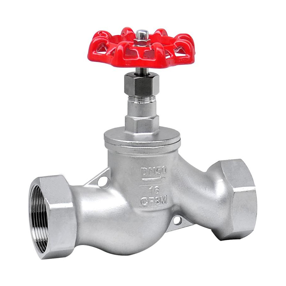
Sizing by pipe diameter is a common, costly field mistake. Many installers simply match the new valve to the existing pipe size. This lazy approach almost always guarantees poor system performance. Decisions must depend strictly on the required flow rate (GPM) and allowable pressure drop (ΔP). We define this mechanical capacity using the Flow Coefficient (Cv). One Cv equals one gallon of water per minute passing through the unit at a one PSI pressure drop.
You must use the standard sizing formula to find the correct Cv. The basic equation is: Cv = Q / √(ΔP / G). In this specific formula, Q represents your flow rate in GPM. The ΔP stands for the targeted pressure drop in PSI. Finally, G represents the specific gravity of your hydronic fluid. Pure water has a specific gravity of exactly 1.0. Adding glycol mixtures will alter this variable slightly during calculation.
Experience teaches us the severe risks of incorrect sizing. You face distinct mechanical problems whether you oversize or undersize the unit.
Oversized Risks: The unit operates dangerously near the closed position constantly. This causes erratic control resolution commonly known as "hunting." It also accelerates seat wear through a destructive process called wire drawing. High-velocity fluid essentially carves grooves into the metal seat.
Undersized Risks: The internal restriction creates excessive fluid velocity instantly. This leads directly to choked flow conditions within the pipe. You will experience destructive cavitation, severe mechanical vibration, and disruptive system noise. Vapor bubbles form and collapse violently against the metal trim.
We recommend a very simple selection rule of thumb. Calculate your required operational Cv carefully first. Then, select a flow regulation valve where this calculated Cv falls between 50% and 70% of the maximum rated travel. This specific sweet spot guarantees optimal control authority. You maintain ample room to modulate flow up or down as building loads change.
Material selection directly impacts system longevity and reliability. You must align body and trim materials with actual operating conditions. Always consider system pressure, peak fluid temperature, and chemical concentrations.
Material Option | Common HVAC Applications | Key Performance Advantages | Application Limitations |
|---|---|---|---|
Bronze / Brass | Commercial hydronic systems, chilled water loops, low-pressure hot water. | Highly cost-effective, readily available, durable under standard HVAC operating conditions. | Not suitable for highly corrosive fluids, acidic environments, or high-pressure steam. |
Stainless Steel | High-temperature steam lines, corrosive industrial environments, harsh chemical processes. | Exceptional corrosion resistance, handles extreme pressure and sudden temperature variations easily. | Higher initial purchase cost compared to standard brass or bronze alternatives. |
Bronze and brass remain the standard for most commercial hydronic systems. They manage chilled and hot water loops reliably for decades. Stainless steel becomes absolutely necessary for high-temperature steam applications. It also survives aggressive corrosive environments perfectly without degrading.
Next, consider your specific actuation readiness. Your mechanical hardware needs a reliable electronic actuator to function automatically. Carefully detail the physical linkage and stem stroke requirements. The actuator stroke must match the valve stem travel exactly. A physical mismatch prevents the unit from fully opening or closing correctly.
Discuss fail-safe mechanisms early during your specification phase. Spring return actuators automatically drive the mechanism to a safe position during power losses. Non-spring return actuators simply remain in their last commanded position. Your specific choice depends entirely on building safety requirements. Additionally, verify control signal matching carefully. Building management systems (BMS) output very specific electronic signals. Common variants include 0-10V proportional, 4-20mA, or floating point control. The chosen actuator must interpret these signals flawlessly to modulate flow.
Installation execution determines operational success or failure. Even perfectly sized equipment fails if installed incorrectly on site. Orientation and flow direction require absolute attention from the installer.
Stress the critical nature of the cast-in flow arrow. Manufacturers cast a directional arrow directly onto the brass or steel body. Flow must typically enter underneath the internal plug. This upward fluid pressure assists the actuator when pulling the valve open. It also prevents violent mechanical chatter when driving the plug closed. Installing it backward damages the stem seal quickly. It also puts immense strain on the actuator gears.
Stem orientation also dictates long-term mechanical reliability. We strongly recommend installing the unit so the stem points vertically upward. You may angle it up to a maximum of 45 degrees if tight space demands it. Never install the unit completely upside down. An inverted stem allows abrasive system debris to accumulate inside the packing gland. This poor orientation also lets leaking fluid drip directly into the sensitive electronic actuator housing.
Field expertise highlights strict threading and sealing rules. Warn your piping installers against the excessive use of PTFE tape. Heavy applications of liquid pipe dope also pose severe internal risks. Excess sealing material can extrude into the internal body cavity. It will eventually harden and damage the precision seating surface. Specify using a wrench only on the hex closest to the attaching pipe. Gripping the opposite side can easily distort the brass body during tightening.
System flushing is an absolute necessity before commissioning. You must flush the entire piping network before installing the final control device. Construction debris, welding slag, and sharp metal shavings circulate through new pipes constantly. This coarse debris easily destroys precision-machined brass trim. Flush the lines thoroughly using bypass loops to protect your physical investment.
Choosing the right hardware supplier minimizes unexpected project risks. Do not evaluate suppliers based on unit price alone. Look closely at their technical documentation and strict compliance standards.
Demand clear, published Cv ratings from any prospective manufacturer. They must provide accurate pressure-temperature (P-T) degradation charts. You should also verify their official ANSI class leakage ratings. Knowing whether a unit meets Class IV or Class VI leakage standards is vital. Strict leakage tolerances prevent costly energy waste during prolonged off-cycles.
Evaluate the manufacturer's warranty terms thoroughly before ordering. A strong, multi-year warranty indicates deep confidence in product engineering. Check the availability of replacement parts before finalizing the purchase. You will eventually need packing repair kits or replacement actuators. Sourcing these replacement components easily saves major maintenance headaches years later.
Balance premium brand names against your actual project schedules carefully. Premium brand names often carry frustratingly extended lead times. You might need parts immediately to meet rigid construction deadlines. Standard-compliant equivalents often match premium performance perfectly in the field. They might offer much faster delivery times to your job site. Evaluate equivalents based strictly on published technical specifications rather than just brand recognition.
Let us summarize the core decision-making sequence for these crucial components. Follow these exact ordered steps to guarantee field success:
Calculate the required Cv accurately based on flow rate and allowable pressure drop.
Select the correct body and trim material for your specific fluid conditions.
Verify actuator compatibility regarding physical stroke limits and electronic control signals.
Adhere strictly to flow direction arrows and vertical installation best practices.
Your next step requires decisive engineering action. We encourage all buyers to consult their system flow schematics immediately. Utilize official manufacturer sizing charts to double-check your initial numbers. If you feel uncertain, contact a specialized fluid control engineer. They can verify your math and material choices expertly. Complete this crucial verification step before you issue any formal purchase order.
A: Yes, provided the body material, trim, and O-ring seals (e.g., EPDM) are rated for the temperature extremes and glycol mixtures of both systems.
A: This is typically evidence of cavitation or flashing due to an undersized valve (excessive pressure drop) or installation backwards against the designed flow direction.
A: With proper sizing, regular water treatment (to prevent scaling), and correct installation, the mechanical valve body can last 15-20+ years, though actuators and stem packings may require earlier servicing.


