


Views: 0 Author: Site Editor Publish Time: 2026-07-08 Origin: Site


Underground tunneling constantly pushes the limits of civil engineering. Severe spatial constraints and high-vibration environments demand flawless fluid control mechanisms. Shield machinery operates in some of the most unforgiving physical conditions on Earth. Standard rising-stem valves pose a critical hazard in these cramped spaces. They require significant vertical clearance during operation. Exposed stems can easily strike tunnel walls or suffer devastating damage in confined operational shafts.
The non-rising stem gate valve acts as the standard specification for underground flow control. It successfully balances robust pipeline isolation with a completely static vertical footprint. You gain highly reliable performance without sacrificing precious headroom. This guide systematically explores the engineering principles behind these space-saving devices. We will carefully examine crucial material standards, configuration trade-offs, and practical risk mitigation strategies. You will learn exactly how to select the right flow isolation component for your specific heavy civil engineering application.
Spatial Efficiency: NRS gate valves maintain a fixed operating height, making them mandatory for shield machinery and compact tunnel utility lines.
Debris Protection: Internal stem threading protects critical moving parts from airborne dust, muck, and corrosive slurry common in tunneling.
Trade-off Management: The inherent lack of visual position indication in NRS valves must be mitigated with mechanical indicators or electronic limit switches.
Specification Focus: Material selection (e.g., EPDM-encapsulated wedges, ductile iron bodies) and pressure class alignment are non-negotiable for long-term underground reliability.
Tunnel construction leaves absolutely zero room for mechanical interference. Equipment must operate within strictly predefined cylindrical boundaries. Vertical clearance realities dictate strict engineering choices underground. Traditional valves extend upward as they open. This upward travel requires dynamic overhead space. A non-rising configuration relies on internal stem threading. The valve stem rotates in place to pull the wedge upward. It never protrudes beyond the valve bonnet. The overall height remains entirely static during full actuation. This static envelope prevents dangerous collisions. It keeps the mechanism clear of tunnel walls, moving gantries, and adjacent utility piping.
Underground sites present massive environmental hazards. Airborne tunnel dust, abrasive grit, and liquid slurry quickly destroy exposed machinery. Keeping the stem threads internal offers a massive operational advantage. The vulnerable threads sit safely inside the valve body. They remain continuously bathed in the working fluid. In specialized designs, multiple O-rings fully isolate the stem from external elements. This internal placement prevents the disastrous buildup of abrasive muck. Exposed threads on standard components routinely jam when coated in dried bentonite slurry. Internalizing the mechanism drastically extends the functional lifespan of the equipment.
Tunnel Boring Machines (TBMs) represent marvels of compact engineering. Every square inch inside a TBM serves a distinct purpose. Integrating a shield machinery valve requires microscopic attention to physical footprints. TBMs feature dense hydraulic and slurry transport networks. Massive volumes of pressurized fluid move through very tight corridors. Engineers must place isolation points close to bulkheads and critical pumps. Standard upward-traveling components simply cannot physically fit inside these nested pipe galleries. Space-saving static designs allow engineers to build tighter, more efficient fluid routing networks inside the shield.
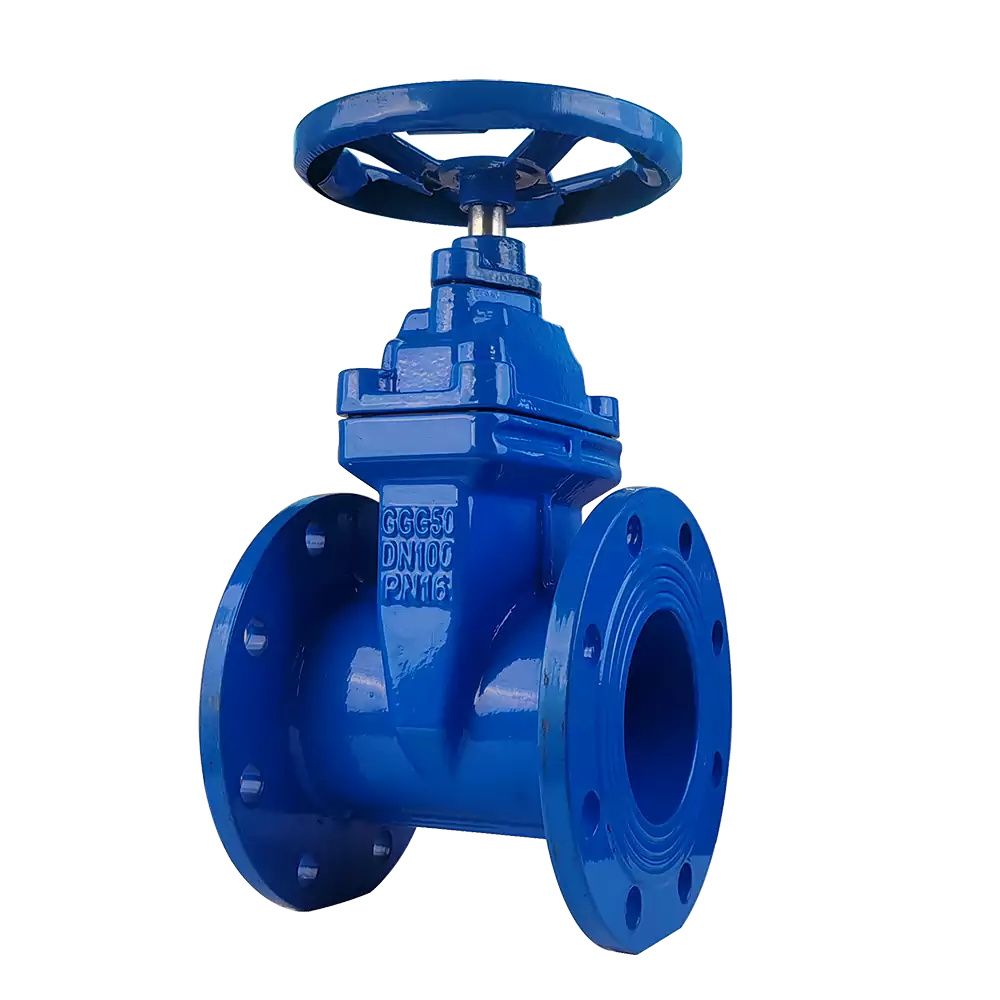
Every engineering choice carries a distinct compromise. The primary drawback of a static stem design remains visual feedback. Operators cannot visually confirm whether the pipeline is open or closed from a distance. You cannot simply glance at the pipe gallery to verify fluid isolation. This "blind spot" complicates rapid safety checks. Maintenance crews must possess absolute certainty before breaking pipeline flanges. Therefore, you must deliberately address this feedback gap during the specification phase.
Selecting the correct mechanism requires balancing space against visibility. We use a structured decision matrix to evaluate these parameters.
Configuration Type | Primary Advantage | Major Limitation | Ideal Tunnel Application |
|---|---|---|---|
Rising Stem (OS&Y) | Instant visual confirmation of open/closed status. | Requires substantial vertical clearance for stem travel. | Above-ground staging areas and unconstrained surface pumping stations. |
Non-Rising Stem (NRS) | Maintains a strictly static, compact vertical footprint. | Lacks native visual position indication. | TBM interiors, underground shafts, and confined utility lines. |
A modern tunnel construction gate valve utilizes advanced engineering workarounds to solve this visibility problem. Manufacturers offer integrated mechanical position indicators. These attach directly to the stem and display a simple dial readout. For automated environments, engineers retrofit IP68-rated electronic limit switches. These rugged switches send real-time position data back to the central control room. Advanced systems also utilize SCADA-connected torque sensors. These sensors detect exactly when the wedge seats firmly against the bottom of the body. You achieve precise status monitoring without sacrificing the necessary compact footprint.
Specifying heavy civil equipment requires rigorous technical evaluation. You must align internal components directly to the anticipated fluid characteristics. Mismatched components fail rapidly under severe underground conditions. We break down the evaluation process into three critical engineering criteria.
Wedge Design and Sealing Mechanism: You must first evaluate the fluid composition. Clean water networks and light slurry lines benefit from resilient-seated wedges. These feature an EPDM rubber encapsulation. The rubber gently compresses against the valve body to provide a bubble-tight seal. It easily absorbs tiny suspended particles. High-abrasion applications require a different approach. Heavy muck lines demand robust metal-seated wedges. Metal seats resist the brutal scouring action of rock particles. Additionally, you must demand a straight-through bore design. A straight bore minimizes pressure drops across the network. It completely prevents debris accumulation by eliminating bottom cavities.
Pressure Ratings and Flow Dynamics: Deep shaft operations encounter extreme hydrostatic pressures. Your specification must directly match these dynamic forces. We utilize strict pressure class frameworks. PN10 systems handle up to 10 bar of pressure safely. Deeper tunnels often require PN16 classes or higher API standards. You must account for sudden pressure surges. Surges frequently occur when massive slurry pumps cycle on and off. The body wall thickness must withstand these sudden hydraulic shockwaves.
Actuation Compatibility: Tunneling projects increasingly rely on automation. Assess how easily the unit transitions from a manual handwheel to an automated actuator. Heavy civil operations often shift from manual operation during setup to electric actuation during active boring. The top flange must conform to ISO 5210 standards. Standardized flanges allow rapid mounting of pneumatic or electric drives. You must ensure the chosen actuator delivers sufficient torque to break the wedge free from compacted sediment.
Harsh underground conditions mercilessly test material integrity. Continuous vibrations from boring heads radiate through the entire pipe network. Standard gray cast iron shatters under these extreme tensile loads. Ductile iron serves as the undisputed industry standard for tunnel applications. Specifically, ASTM A536 ductile iron delivers exceptional impact resistance. The unique nodular graphite structure allows the metal to slightly flex rather than crack. This elasticity proves vital when ground shifts naturally misalign massive pipe segments.
Corrosion presents another relentless threat to underground infrastructure. Groundwater highly varies in chemical composition. Crews frequently encounter high salinity, aggressive moisture, and extreme pH levels. Unprotected metal dissolves rapidly in these harsh trenches. Fusion-bonded epoxy (FBE) coatings provide mandatory defense mechanisms. Manufacturers apply FBE both internally and externally. The epoxy powder melts and permanently fuses to the heated ductile iron. This creates a dense, impenetrable barrier against corrosive elements. The FBE coating must maintain a minimum thickness of 250 microns to guarantee long-term protection.
You cannot blindly trust marketing brochures when specifying heavy equipment. Engineering teams must rigorously verify all manufacturer claims. Demand comprehensive ISO 9001 quality management documentation. Require API or AWWA compliance certificates for every batch. Furthermore, insist on reviewing factory pressure-test reports. Manufacturers must provide successful hydrostatic shell test results. They must also document rigorous seat testing procedures. These tests prove the unit can handle absolute maximum rated pressures without showing a single drop of leakage. Strict compliance verification prevents catastrophic flooding events deep underground.
Even the most robust equipment requires calculated maintenance strategies. Underground systems face unique operational realities. You must proactively plan for sediment management. Suspended solids inevitably settle when fluid velocity drops. This sediment builds up at the bottom of the body in the "sump" area. Compacted sediment prevents the wedge from seating completely. You must establish strict routine flushing protocols. Crews need to regularly open the pipeline fully to maximize flow velocity. High-velocity fluid scours the internal cavity clean. This simple operational habit prevents dangerous incomplete closures.
Stem seals naturally wear down from repeated mechanical friction. Replacing these seals traditionally requires entirely draining the pipeline. This process causes unacceptable system downtime during active tunnel boring. You should specify designs offering under-pressure seal replacement capabilities. Premium designs feature a specialized backseating arrangement. Fully opening the unit creates a tight mechanical seal between the stem collar and the bonnet. This isolates the upper O-rings from the internal fluid pressure. Maintenance crews can safely swap worn O-rings without shutting down the entire pumping network.
Vendor selection carries as much weight as technical specifications. Partnering with inexperienced manufacturers introduces severe project risks. Utilize a strict checklist when shortlisting potential equipment suppliers.
Material Traceability: The vendor must provide documented origin tracking for all ductile iron pours and raw materials.
Spare Parts Availability: Ensure the supplier maintains localized inventory for rapid deployment of replacement wedges and seal kits.
Proven Track Record: Demand case studies demonstrating successful integration in comparable heavy civil engineering or TBM projects.
Engineering Support: The manufacturer should offer direct technical consultation for actuator sizing and automation integration.
Choosing a static-stem flow control device for tunnel construction represents a highly calculated engineering decision. You deliberately prioritize spatial efficiency and environmental protection over native visual feedback. By internalizing the mechanical threads, you shield vital moving parts from corrosive slurry and abrasive tunnel dust. This configuration remains absolutely mandatory for cramped shield machinery and high-density underground utility networks.
Engineering and procurement teams must take immediate action to secure the right equipment. Begin by auditing your exact spatial tolerances along the tunnel walls and TBM gantries. Analyze the anticipated fluid abrasion levels to determine between resilient and metal-seated designs. Finally, map out your long-term automation needs. Gather these distinct parameters before requesting manufacturer specification sheets. Precise upfront planning ensures you deploy an underground isolation system capable of surviving the harshest tunneling conditions.
A: You cannot determine the position by simply looking at the stem length. Instead, you must rely on supplementary devices. Engineers install mechanical post indicators or dials directly onto the operating nut. For automated systems, IP68-rated electronic limit switches track the precise wedge location. These rugged switches relay real-time open or closed status directly to the central control room.
A: Yes, they routinely manage varied underground fluids. However, you must specify the correct internal components. Resilient-seated designs work best for water and light slurry, providing tight shut-offs against small particles. If you are pumping heavy, highly abrasive muck containing large rock fragments, standard designs may fail. Those extreme applications usually require specialized heavy-duty knife gate configurations.
A: Harsh underground environments severely accelerate component wear. You should establish a strict baseline maintenance frequency. Perform monthly torque tests to ensure the handwheel operates smoothly without binding. Conduct quarterly visual inspections of the external FBE coating to identify corrosion early. Finally, recalibrate any attached electric actuators every six months to guarantee precise closure limits.


