


Views: 0 Author: Site Editor Publish Time: 2026-09-06 Origin: Site


Backflow in chemical processing presents a severe operational risk. Reverse flow compromises system integrity rapidly, causing cross-contamination, equipment damage, or hazardous environmental releases. Engineers face a strict mechanical challenge on the plant floor. You must specify a non-return valve that resists highly aggressive media while operating efficiently under specific flow conditions. It cannot induce excessive pressure drops or restrict pump performance. The lift check valve provides a highly reliable solution for high-pressure and high-flow velocity systems. Success requires evaluating multiple interacting factors. You must balance cracking pressure, spring tension, and metallurgical compatibility. We will explore how to select the right valve for chemical applications, covering operational mechanics, material selection, and fluid dynamics. You will learn how to balance low cracking pressure with positive sealing to maintain plant safety.
Precision in Flow Control: A low cracking pressure check valve minimizes energy loss and pressure drop but requires precise spring and seat engineering to ensure a positive seal against reverse flow.
Material Selection is Non-Negotiable: Specifying a chemical process check valve requires matching both the body and the internal trim (seats, springs, discs) to the specific corrosive profile and temperature of the process media.
Orientation Dictates Performance: The functional reliability and actual net cracking pressure of a lift type check valve are heavily influenced by installation orientation (vertical vs. horizontal) and the specific gravity of the fluid.
A successful check valve installation in a chemical plant meets strict performance criteria. It must deliver zero leakage during reverse flow events. It requires minimal maintenance over thousands of operational cycles. It must provide a predictable pressure drop that aligns with the hydraulic model of the piping system. It must ensure regulatory compliance regarding fugitive emissions and pressure vessel codes. Long-term system integrity depends entirely on these factors. A failed non-return valve leads directly to unplanned shutdowns, damaged rotating equipment, and safety incidents.
The internal design of a lift type check valve relies on fundamental fluid dynamics. Upstream fluid pressure lifts the internal disc or piston off the seat. This action allows the chemical media to flow through the valve body. When the forward flow stops or reverses, gravity and internal spring force return the disc to the closed position. This creates a reliable mechanical barrier against backflow.
These valves typically feature a globe-style body architecture. The fluid enters the inlet port, turns 90 degrees upward through the seat ring, and turns 90 degrees again to exit the discharge port. This tortuous flow path makes them inherently suited for severe service conditions. They handle high-pressure and high-velocity applications easily. Common field deployments include high-pressure steam lines, boiler feedwater systems, petrochemical transfer manifolds, and aggressive chemical processing loops. The internal guided piston prevents the disc from shifting off-center during highly turbulent flow, ensuring the seating surfaces align perfectly upon closure.
Chemical media rarely behaves like clean water. Fluid viscosity significantly impacts how the internal components react. Highly viscous fluids require more kinetic energy to lift the piston fully. Specific gravity alters the buoyancy of the internal metallic or plastic components. Particulates or suspended solids complicate the flow profile further. Solids can jam unguided discs or rapidly erode soft elastomeric seating materials.
The globe-style flow path directly affects the flow coefficient (Cv) of the piping loop. A lift check creates more resistance than a straight-through swing check design. You must account for this inherent pressure drop during the design phase. You cannot simply match the nominal line size of the pipe. You must calculate the exact Cv required for the specific chemical media and flow rate. Proper sizing ensures the fluid maintains enough velocity to keep the disc fully lifted against the top stop. This prevents premature wear on the internal guides caused by the disc hovering in the flow stream.
High-viscosity fluids require larger valve sizes to maintain acceptable pressure drops.
Suspended solids demand hardened seating surfaces to prevent rapid erosion.
Pulsating flow requires guided pistons to dampen the mechanical shock on the internal components.
Low-velocity lines require lighter internal springs to ensure the disc fully opens.
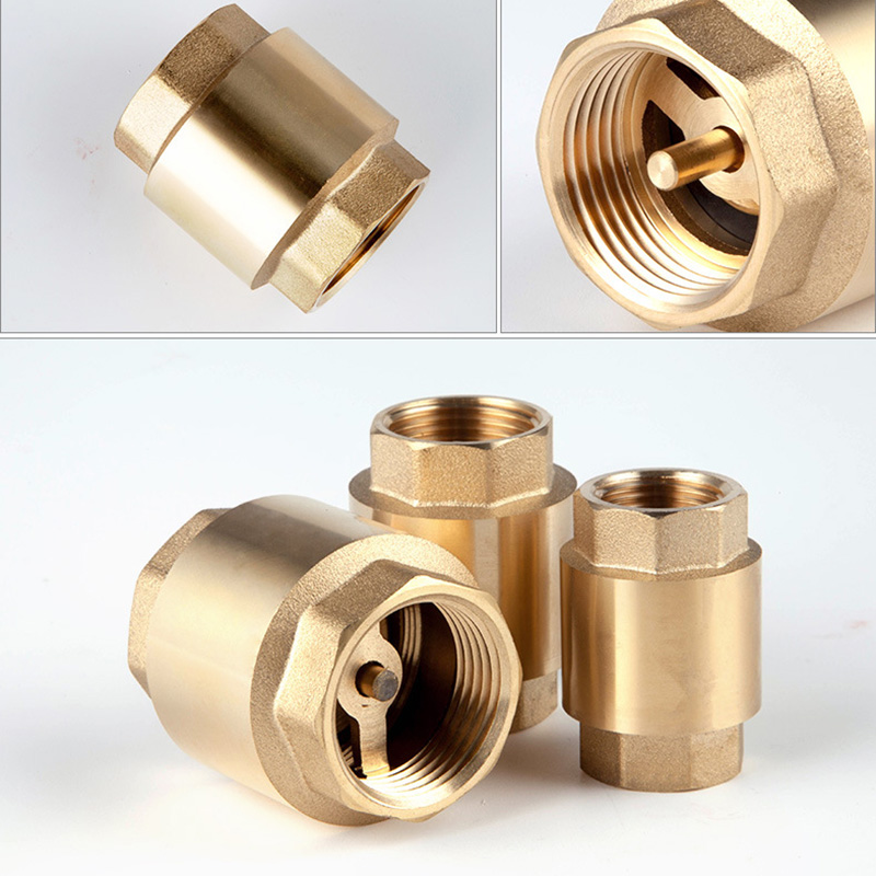
Valve opening physics directly connect to system-level energy efficiency. Every unit of pressure required to open a valve represents electrical energy consumed by the centrifugal or positive displacement pump. You must evaluate how cracking pressure impacts pump sizing, motor horsepower, and overall loop performance.
Cracking pressure is the minimum upstream pressure required to unseat the disc and initiate forward flow. Overcoming internal spring tension and the static weight of the disc requires mechanical force. In high-stakes chemical environments, this metric dictates system responsiveness and hydraulic efficiency.
A low cracking pressure check valve is often necessary for specific operational scenarios. Low-flow applications lack the kinetic energy to push open heavy standard springs. Systems with limited pump head availability cannot afford high pressure drops across the valve seat. Gravity-fed chemical dosing lines require minimal mechanical resistance to function correctly, often relying on valves with cracking pressures below 0.25 psi.
Reseal pressure is equally critical in chemical processing. Reseal pressure is the exact point where the valve closes completely and establishes a seal. A valve might crack open at 0.5 psi but reseal at 0.1 psi. In chemical loops, the valve must reseal before reverse flow actually begins. A delayed reseal allows hazardous media to slip backward through the piping, potentially contaminating upstream batch tanks.
Engineering always involves mechanical compromise. Lower spring tension reduces the cracking pressure, saving pump energy. However, a weak spring compromises the speed and force of the mechanical seal. During rapid flow reversal, a weak spring might not close the disc fast enough. This delay causes hydraulic shock, commonly known as water hammer, which can rupture pipe joints.
Seating materials play a major role in resolving this trade-off. Metal-to-metal seats require high backpressure to force a tight, leak-free seal. A low cracking pressure valve with metal seats will likely leak at low backpressures. Elastomeric or soft seats solve this problem effectively. Materials like PTFE or Viton deform slightly under very light pressure. They achieve a bubble-tight seal even when the reverse pressure is minimal, compensating for the weaker spring force.
Installation orientation alters the minimum recommended net cracking pressure. Vertical flow (upward) forces the fluid to lift the entire static weight of the disc assembly. Gravity works against the forward flow but helps close the valve rapidly upon pump shutdown. Horizontal installation changes the physics entirely. The fluid only fights the spring tension and the sliding friction of the guides. The weight of the disc rests on the valve body guides rather than opposing the flow.
You must calculate the actual net cracking pressure based on the fluid's specific gravity. Heavy fluids like concentrated sulfuric acid exert more lifting force per square inch than lighter hydrocarbons like hexane. If you install a valve vertically, you must add the static weight of the disc to the spring rate to determine the true opening pressure. Downward vertical flow is generally prohibited for standard lift checks because gravity would pull the valve open permanently, defeating its purpose.
Material choices dictate the physical lifespan and safety of the piping system. They also ensure regulatory compliance with standards like ASME B16.34 and API 598. Selecting the wrong alloy or polymer leads to rapid corrosion, structural failure, and dangerous chemical leaks.
Metallic options vary widely in their chemical resistance profiles. Standard 316/316L Stainless Steel handles mild corrosives, solvents, and clean water. Duplex stainless steels (like Alloy 2205) offer superior resistance to chloride stress corrosion cracking, making them ideal for brine and marine environments. Monel 400 excels in hydrofluoric acid applications. Hastelloy C276 provides exceptional defense against severe localized corrosion in mixed acid streams. Titanium is mandatory for wet chlorine gas service, where other metals fail in days.
Non-metallic and lined options provide robust alternatives for highly aggressive media. A corrosion resistant check valve often utilizes a cast ductile iron or carbon steel body lined with PTFE or PFA. The thick fluoropolymer lining completely isolates the metal housing from the chemical media. Solid thermoplastics like PVC, CPVC, and PVDF offer extreme corrosion resistance for lower-pressure systems. These solid plastics work perfectly where high temperatures are not a factor, eliminating the need for exotic, hard-to-machine metal alloys.
The internal trim must survive the exact same chemical exposure as the valve body. Soft seat materials offer different chemical resistance profiles and temperature limits. PTFE is nearly universally resistant to chemicals but lacks natural elasticity, requiring specific seat designs to seal properly. Viton (FKM) handles many hydrocarbons and acids but swells rapidly in ketones and amines. EPDM works well for caustics, ammonia, and hot water but degrades instantly in petroleum products. Kalrez (FFKM) provides universal chemical resistance and high-temperature stability, acting as the ultimate elastomer for severe service.
Metal-to-metal seats remain mandatory in specific high-wear scenarios. High-temperature chemical vapors will melt or degrade soft elastomers. Abrasive slurries, such as titanium dioxide or catalyst fines, will tear PTFE seats apart in a matter of days. In these applications, hardened metal seats featuring Stellite 6 overlays provide the necessary durability. They sacrifice low-pressure sealing capability for extreme physical toughness and erosion resistance.
Elevated process temperatures reduce the maximum allowable working pressure (MAWP) of the piping system. You must derate the valve based on the maximum operating temperature. Metallic materials lose tensile strength as heat increases. A carbon steel valve rated for 285 psi at ambient temperature handles significantly less pressure at 400°F.
Non-metallic materials derate much faster than metals. A solid PVC valve might hold 150 psi at 73°F. At 140°F, its pressure rating drops to a fraction of that value. PTFE linings can permeate under high heat and pressure, allowing corrosive gases to attack the metal body behind the liner. You must consult specific pressure-temperature curves for every chemical process check valve before finalizing the engineering specification.
You must validate if a lift check is the correct mechanical topology for the specific piping loop. Comparing different valve styles ensures optimal system performance. Each design handles fluid dynamics, pressure drops, and mechanical wear differently.
The internal flow paths differ completely between these two common designs. Lift checks use a tortuous globe-style path. Swing checks use a straight-through path. The straight path of a swing check minimizes pressure drop in steady-flow lines, making them suitable for long transfer pipelines.
However, lift checks are vastly superior for frequent flow reversals. They handle pulsating flow from reciprocating pumps, diaphragm pumps, and metering pumps exceptionally well. The guided piston dampens the internal movement. Swing checks tend to slam violently in pulsating flow. This slamming damages the internal hinge pin and shatters the seating surface. Lift checks eliminate the hinge pin entirely, removing the most common mechanical failure point found in non-return valves.
Inline (axial) check valves feature a spring-loaded disc moving parallel to the flow stream. They typically offer lower inherent cracking pressures and a more streamlined flow path. This makes them ideal for low-flow applications where pressure drop must be minimized. Dual disc (wafer) valves split the disc in half, folding like butterfly wings. They offer compact, space-saving benefits, fitting easily between standard pipe flanges.
Traditional lift checks contrast these designs by offering robust, high-pressure capabilities and superior mechanical stability. They provide excellent sealing due to the heavy guided piston. They also offer unmatched ease of maintenance. You can access the internals of a lift check through the top bolted cover. Inline and wafer valves require complete removal from the piping system for any internal inspection or seat replacement.
Valve Type | Flow Path | Pressure Drop | Pulsation Handling | Inline Maintenance |
|---|---|---|---|---|
Lift Check | Globe-style (Tortuous) | Moderate to High | Excellent (Dampened) | Yes (Top-entry) |
Swing Check | Straight-through | Low | Poor (Prone to slamming) | Yes (Top-entry) |
Inline Spring | Straight (Axial) | Moderate | Good | No (Must remove from line) |
Dual Disc (Wafer) | Straight-through | Low | Moderate | No (Must remove from line) |
Post-installation operational headaches occur frequently if the initial sizing and selection are incorrect. Addressing common mechanical failure modes during the design phase prevents system downtime and hazardous leaks.
Excessive pressure drop poses a major risk to rotating equipment. It leads directly to pump cavitation. Cavitation destroys pump impellers rapidly by collapsing vapor bubbles against the metal surfaces. It also causes process inefficiency by restricting chemical throughput and increasing batch times.
Mitigate this by sizing the valve based strictly on Cv calculations. Never simply match the nominal line size of the pipe. Calculate the required flow coefficient based on the minimum and maximum anticipated flow rates. Ensure the pump has sufficient head to overcome the valve's mechanical resistance while maintaining the required downstream pressure for the process.
Valve chatter is the rapid, destructive oscillation of the disc against the seat. It occurs when the fluid flow velocity is insufficient to hold the disc fully open against the top stop. Chatter causes premature wear on the guides and destroys soft elastomeric seats. Delayed closing causes hydraulic shock, commonly known as water hammer. Water hammer ruptures pipe joints, blows out gaskets, and damages sensitive instrumentation.
Mitigate these risks by selecting the correct internal spring rate. Ensure minimum flow velocities are met to keep the valve fully open during normal operation. If the flow rate varies widely, utilize internal damping mechanisms. Dashpots or specialized guided pistons slow the closing speed slightly. This prevents the sudden shockwave of water hammer while still closing fast enough to prevent massive backflow.
Chemical aggressiveness dictates the required maintenance schedule. Highly corrosive media requires frequent internal inspections to verify liner integrity and seat condition. Top-entry lift check designs provide a significant advantage for plant maintenance teams. They allow for complete inline maintenance. Technicians isolate the line, unbolt the top cover, remove the piston assembly, and inspect the seating surfaces.
They perform this work without removing the heavy valve body from the piping flanges. Establish a strict preventative maintenance schedule based on cycle frequency and chemical severity. Replace soft elastomers annually in aggressive chemical service. Inspect metal guides for galling, scoring, or particulate buildup. Document all internal wear patterns to adjust future material specifications and improve plant reliability.
The lift check valve remains the optimal choice for chemical processes requiring robust backflow prevention. It excels in high-pressure, pulsating, or high-velocity environments where other valve designs fail mechanically. Selection requires solving a simultaneous engineering equation. You must balance the required net cracking pressure, acceptable pressure drop, and strict metallurgical compatibility with the process fluid.
Take the following actions to specify your next valve correctly:
Calculate your exact flow conditions, including minimum flow, maximum flow, and fluid specific gravity.
Determine the precise operating temperature to apply correct pressure derating factors to the valve body.
Consult chemical compatibility charts for both the valve body alloy and the internal elastomeric seats.
Request Material Test Reports (MTRs) from manufacturers to verify alloy authenticity and heat numbers.
Specify top-entry designs if your piping layout restricts the easy removal of flanged components.
A: The standard cracking pressure typically ranges between 0.1 to 0.5 psi for standard springs. Engineers can customize this metric by installing different spring rates to meet specific low cracking pressure requirements for gravity-fed or low-flow chemical loops.
A: Yes, but typically only for upward flow. Gravity pulls the internal disc downward. This alters the net cracking pressure because the fluid must lift the disc's static weight. Downward flow requires specialized spring configurations to prevent the valve from staying permanently open.
A: Selection depends entirely on the acid concentration and operating temperature. Alloy 20 handles many sulfuric acid concentrations well. Hastelloy C provides resistance at higher temperatures. PTFE-lined valves offer excellent protection for highly concentrated sulfuric acid at lower temperatures.
A: Chatter occurs when the fluid flow velocity is insufficient to hold the internal disc fully open against the stop. The disc bounces rapidly against the seat. This usually means the valve is oversized for the application or the internal spring rate is too high.
A: Lower spring tension provides less mechanical force to assist the seal at low backpressures. This makes the choice of seat material critical. Using soft elastomers like PTFE or Viton ensures a bubble-tight shutoff even when reverse pressure is minimal.
A: The difference lies in the internal guiding mechanisms. Piston types use a guided cylinder, making them better for clean, high-pressure fluids. Ball types use a free-floating sphere. Ball checks handle highly viscous media or fluids with suspended solids much better.


