


Views: 0 Author: Site Editor Publish Time: 2026-09-27 Origin: Site


Specifying hardware for aggressive media requires balancing fluid dynamics, material compatibility, and actuation requirements. A single misapplication often leads to unplanned downtime, fugitive emissions, cross-contamination, or catastrophic blowouts. The stakes in chemical processing remain severe. You need an engineering-focused framework for evaluating isolation, regulation, and directional flow control. This ensures the specified hardware aligns directly with process realities, Piping and Instrumentation Diagrams (P&IDs), and lifecycle expectations. Proper valve selection for chemical plants determines operational safety and system efficiency. We will break down the mechanical realities of matching specific geometries to challenging chemical environments, ensuring your infrastructure withstands the harshest operating conditions without compromising the pressure boundary.
Function Dictates Form: Isolation (ON/OFF) requires different mechanical geometries than flow regulation; misapplying a gate valve for throttling accelerates seat wear and failure.
Media Compatibility is Non-Negotiable: Chemical concentration, temperature, and particulate load must dictate both the body metallurgy and the soft-goods (seats and seals) selection.
Pressure Drop and Flow Dynamics: Understanding the inherent pressure drop (Cv value) of globe versus ball valves is critical for maintaining system efficiency, preventing cavitation, and optimizing pump energy costs.
Lifecycle Cost Outweighs Initial Price: Evaluating valves based on mean time between failures (MTBF), performance metrics, and ease of inline maintenance yields a lower long-term expense than sourcing based on upfront unit cost.
Establishing exact baseline and peak operating pressures, temperature extremes, and flow rates forms the foundation of any specification process. Engineers must define the maximum allowable working pressure (MAWP) and the design temperature limits before evaluating mechanics. Operating conditions in chemical facilities rarely remain static. Thermal cycling, pressure spikes during pump start-ups, and varying flow velocities directly impact mechanical integrity. Documenting these parameters ensures the selected hardware withstands transient conditions.
Auditing the chemical media requires a granular understanding of fluid characteristics. Corrosiveness dictates metallurgy. Handling 98% sulfuric acid demands entirely different materials than processing sodium hydroxide or hydrochloric acid. Viscosity influences the flow coefficient requirements, while the presence of abrasive particulates or crystallizing fluids dictates the internal geometry. Fluids that polymerize or crystallize upon cooling require specific cavity-free designs or steam-jacketed bodies to prevent internal blockages and mechanical binding.
Categorizing flow control requirements simplifies the initial selection phase. Systems generally demand positive isolation for tight shut-off, precise flow regulation for throttling, or directional control for backflow prevention. While specialty designs like butterfly, diaphragm, and plug valves serve specific niche applications, the core infrastructure relies heavily on the primary four geometries. Matching the functional requirement to the mechanical design prevents rapid degradation. Using an isolation valve for throttling induces high-velocity flow across the seating surfaces, causing rapid erosion.
Translating Piping and Instrumentation Diagrams (P&IDs) to physical hardware requires strict attention to detail. P&IDs dictate the required valve type, fail-safe position (Fail Open, Fail Closed, or Fail Last), and control logic. Engineers must ensure the specified hardware matches the engineered flow control strategy. A mismatch between the P&ID intent and the installed hardware creates severe operational hazards, particularly during emergency shutdown (ESD) sequences.
Environmental compliance and safety mandates heavily influence modern specifications. Fugitive emissions represent a significant regulatory and safety risk in chemical processing. Evaluating hardware through the lens of standards like API 622 or ISO 15848 ensures the integration of low-emission packing systems. These live-loaded packing designs maintain continuous compression on the stem seals, compensating for wear and thermal cycling to prevent volatile organic compounds (VOCs) from escaping into the atmosphere.
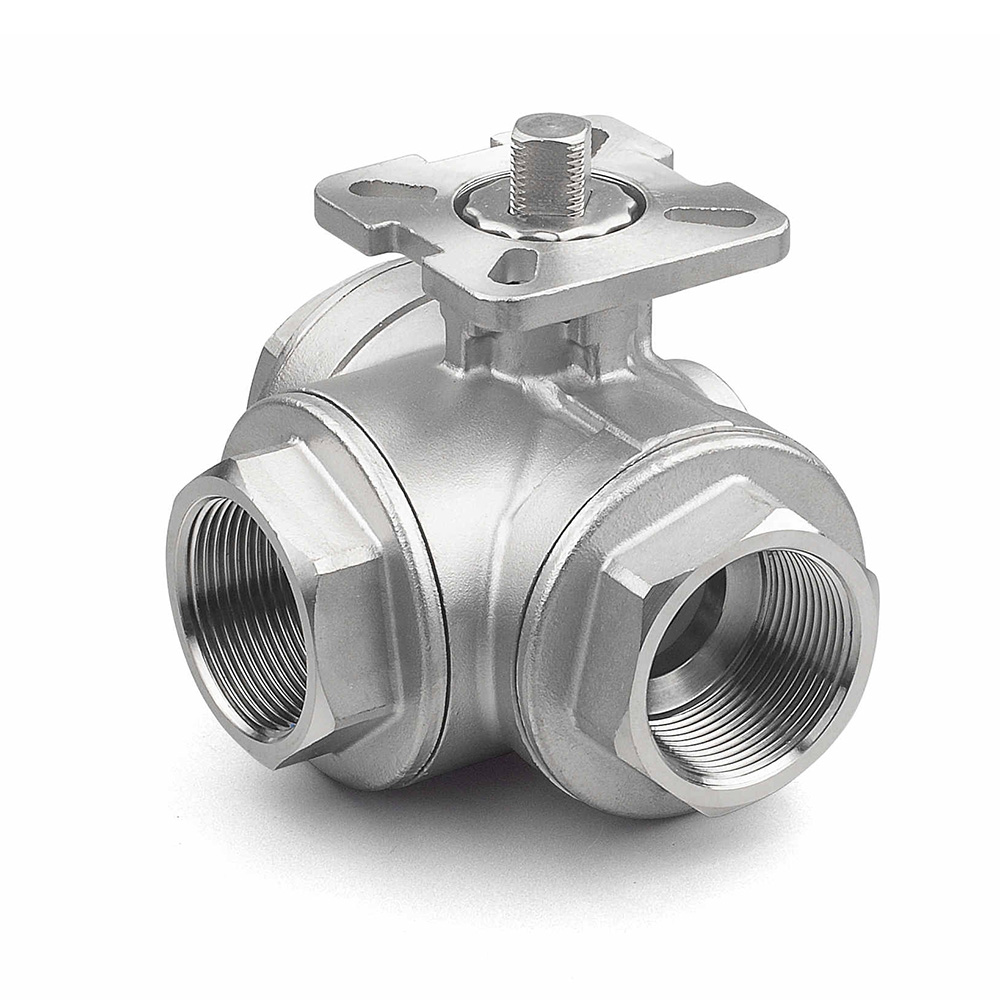
The quarter-turn mechanism provides rapid actuation and immediate flow control. A ball valve for chemical processing features a straight-through flow path, resulting in an exceptionally low pressure drop and high flow capacity. Floating designs rely on line pressure to push the ball against the downstream seat, ensuring a tight seal in low-to-medium pressure applications. Trunnion-mounted designs secure the ball mechanically at the top and bottom. This configuration absorbs the line pressure thrust, reducing operating torque and preventing seat crushing in high-pressure scenarios.
These units excel in scenarios requiring rapid ON/OFF isolation. They handle clean corrosive fluids efficiently and allow operators to isolate equipment for maintenance without interrupting connected units. Their low operating torque makes them ideal candidates for integration with automated pneumatic or electric actuators. Automated quarter-turn packages provide reliable remote operation, integrating seamlessly into distributed control systems (DCS) for emergency isolation sequences.
Matching seat materials to the chemical concentration and temperature limits prevents chemical attack and swelling. Polytetrafluoroethylene (PTFE) offers excellent chemical resistance but deforms under high temperatures. Reinforced PTFE (RTFE) incorporates glass or carbon fibers to increase structural integrity and thermal resistance. For higher temperatures or abrasive media, Polyetheretherketone (PEEK) or metal-seated configurations provide the necessary durability. Incorrect soft-goods selection leads to rapid elastomer degradation, resulting in internal leakage and loss of isolation integrity.
Common Seat Materials for Chemical Ball Valves | |||
Material | Temperature Limit | Chemical Resistance | Best Application |
|---|---|---|---|
Virgin PTFE | Up to 400°F (204°C) | Excellent | General corrosive chemicals, low pressure |
RTFE (Glass/Carbon filled) | Up to 450°F (232°C) | Very Good | Higher pressure chemical lines, moderate wear |
PEEK | Up to 500°F (260°C) | Good | High temperature, abrasive chemical slurries |
Metal (Stellite coated) | Up to 1000°F+ (537°C+) | Varies by base metal | Extreme temperatures, heavy particulates |
Implementation risks center around media entrapment in the body cavity. When closed, fluid remains trapped inside the internal bore. In volatile chemical services, ambient temperature increases cause this trapped fluid to expand rapidly. This thermal expansion generates immense internal pressure, potentially causing shell failure. Cavity relief mechanisms, such as vented balls or self-relieving seats, mitigate this risk. Furthermore, standard quarter-turn designs are strictly prohibited for throttling. Partially opening the bore exposes the soft seats to high-velocity flow, causing rapid erosion and permanent sealing failure.
Structural differences between solid, flexible, and split wedges dictate performance in various thermal conditions. Solid wedges offer robust simplicity but remain susceptible to thermal binding in high-temperature lines. Flexible wedges feature a perimeter groove that allows slight deformation, compensating for thermal expansion and preventing the wedge from sticking in the closed position. Split wedges consist of two independent halves that adjust to seat angle variations, providing superior sealing in low-pressure applications. Rising stems provide visual position indication, while non-rising stems suit installations with vertical space constraints.
A gate valve for chemical pipeline applications delivers unrestricted flow when fully open. They dominate large-diameter infrastructure where minimal pressure drop is required to maintain pump efficiency. Their bi-directional sealing capability makes them versatile for bulk isolation tasks. Operators typically deploy them in locations requiring infrequent ON/OFF operation, such as main header isolation, tank farm manifolds, and long-distance transfer lines.
Handling slurries and viscous media requires specific design considerations. Standard wedges can trap particulates in the bottom seat guide, preventing full closure. Knife-gate variations solve this problem by utilizing a sharp-edged disc that cuts through thick media and heavy particulate loads. These specialized units push particulates out of the seating area during closure, ensuring positive isolation in pulp, slurry, and high-viscosity chemical services.
Operational trade-offs include slow actuation speed. The multi-turn requirement prevents rapid emergency isolation. Partially opening the wedge induces wire drawing, where high-velocity fluid erodes the seating surfaces, destroying the isolation capability. Thermal binding remains a significant risk if operators close a solid wedge tightly while the system is hot; as the pipeline cools and contracts, the wedge becomes mechanically locked between the seats, making reopening nearly impossible without damaging the stem.
Internal flow paths heavily influence fluid dynamics. Z-shaped or Y-pattern internal geometries force the fluid to change direction multiple times. This tortuous path inherently causes a high pressure drop but offers superior proportional flow control. The relationship between stem travel and flow rate remains highly predictable, allowing operators to modulate flow precisely. A globe valve for chemical service utilizes this geometry to manage pressure differentials and control flow volumes accurately across a wide operating range.
Matching these units to specific chemical processes optimizes system stability. They serve as the primary choice for cooling water regulation, chemical dosing, and bypass loops. Whenever precise flow modulation around sensitive equipment is necessary, this geometry provides the required control resolution. They also function effectively in boiler feedwater systems and steam regulation, where managing pressure letdown is a continuous operational requirement.
Plug and seat configurations determine the exact flow characteristics. Parabolic plugs provide equal percentage or linear flow curves, suitable for general throttling. Cage-guided trims offer enhanced stability, reducing vibration and noise in high-pressure differential applications. V-port plugs deliver fine control at low flow rates. Selecting the correct trim design prevents premature wear, ensures control loop stability, and extends the operational lifespan of the hardware.
Maintenance realities often dictate selection. The top-entry design allows technicians to replace the internal trim without removing the heavy body from the pipeline, significantly reducing maintenance downtime. However, high-pressure differential chemical services introduce severe cavitation and flashing risks. When localized pressure drops below the fluid's vapor pressure, vapor bubbles form and subsequently collapse, generating shockwaves that destroy metal surfaces. Anti-cavitation trims, featuring multi-stage pressure letdown paths, mitigate this destructive phenomenon.
Mechanical variations dictate how internal geometries interact with different chemical fluids. Swing designs utilize a hinged disc that swings out of the flow path, offering low pressure drop in horizontal lines. Lift designs operate similarly to globe geometries, where flow pushes a piston or disc upward; they excel in high-pressure applications but induce higher pressure drops. Spring-loaded inline designs utilize a spring to assist closure, allowing installation in any orientation and providing rapid response to flow reversal.
Sizing a check valve for chemical process lines requires engineering precision. Sizing based merely on pipe size often leads to failure. Engineers must size these units based on flow velocity to ensure the disc remains fully open and stable during normal operation. If the flow velocity is insufficient to overcome the cracking pressure and hold the disc open, the internal mechanism chatters. This continuous fluttering accelerates hinge pin wear, leading to premature mechanical failure and potential downstream debris contamination.
Fluid compatibility directly impacts internal wear. Highly corrosive or particulate-laden chemical media rapidly degrade internal springs and complex hinges. In these aggressive environments, simpler designs like swing or ball checks perform better. Ball checks utilize a free-floating sphere that rolls out of the flow path, eliminating hinge pins entirely. This makes them highly resistant to particulate binding and ideal for viscous or crystallizing chemical services.
Failure modes require proactive mitigation strategies. Water hammer occurs when a valve closes too slowly, allowing reverse flow to accelerate before the disc slams shut. This generates severe hydraulic shockwaves that rupture piping. Non-slam, spring-assisted designs close rapidly before reverse flow develops, mitigating water hammer. Reverse flow leakage often stems from particulate accumulation on the seating surface. Proper orientation—ensuring vertical lines flow upward—and installing dampening accessories help maintain operational integrity and prevent catastrophic backflow into sensitive process units.
Body material selection forms the primary defense against chemical attack. Standard carbon steel and austenitic stainless steels (like 316L) suffice for mild chemicals and utilities. However, aggressive acids and bases require significant upgrades. High-nickel alloys, including Hastelloy, Monel, and Inconel, provide exceptional resistance to localized pitting, stress corrosion cracking, and aggressive chlorides. For extreme corrosives like hot hydrochloric acid, PTFE or PFA-lined bodies offer the ultimate barrier, combining the structural strength of ductile iron or steel with the chemical inertness of fluoropolymers.
Evaluating soft goods and elastomers requires matching the polymer to the specific chemical concentration and temperature profile. O-rings, packing, and gaskets remain highly susceptible to chemical attack, swelling, and thermal degradation. Fluoroelastomers (FKM) handle many hydrocarbons and acids but fail in ketones and amines. Perfluoroelastomers (FFKM) offer near-universal chemical resistance but come at a premium. Graphite packing provides excellent high-temperature resistance and fire safety but requires careful consideration in oxidizing environments.
Industry standards and certifications guarantee mechanical integrity and safety compliance. Specifying hardware that meets ASME B16.34 ensures rigorous adherence to pressure-temperature ratings and minimum wall thickness requirements. API 608 and API 600 dictate robust design criteria for petrochemical applications. For sour gas or environments containing hydrogen sulfide (H2S), compliance with NACE MR0175 is mandatory to prevent sulfide stress cracking. Adhering to these standards eliminates guesswork and ensures the installed hardware meets global safety benchmarks.
Alloy Selection Guide for Aggressive Chemical Media | |||
Alloy Type | Common Designations | Primary Chemical Resistance | Typical Applications |
|---|---|---|---|
Austenitic Stainless | 316, 316L, 304 | Mild acids, organics, water | General utility, mild solvents, food-grade chemicals |
Duplex Stainless | Alloy 2205, 2507 | Chlorides, stress corrosion | Brine systems, cooling water, moderate acids |
Nickel-Copper | Monel 400 | Hydrofluoric acid, seawater | Alkylation units, marine chemical transport |
Nickel-Molybdenum | Hastelloy C276 | Severe corrosives, wet chlorine | Sulfuric acid processing, aggressive mixed acids |
Challenging the procurement mindset of choosing the cheapest compliant hardware transforms plant reliability. Upfront cost represents a fraction of the financial equation. Investing in severe-service trims, hardened seating surfaces, or superior metallurgy drastically reduces the mean time between failures (MTBF). Frequent maintenance interventions, production downtime, and fugitive emission fines quickly eclipse the initial savings of a budget-grade unit. Prioritizing lifecycle durability ensures continuous production and minimizes hazardous exposure for maintenance personnel.
System efficiency directly impacts pump energy consumption. Every restriction in the piping network forces pumps to work harder. The hidden cost of pressure drops accumulates rapidly in high-volume chemical plants. Selecting high-Cv geometries, such as full-port quarter-turn or unrestricted multi-turn designs, for isolation duties optimizes long-term pump energy consumption. Engineers must calculate the pressure drop across the entire system to ensure the selected hardware does not create artificial bottlenecks that drive up electrical costs.
Actuation and automation readiness require careful torque analysis. Retrofitting manual hardware for automation in the field often introduces alignment issues and torque mismatches. Specifying actuated packages—whether pneumatic, hydraulic, or electric—directly tailored to the valve's specific torque curve ensures reliable operation. The actuator must provide sufficient breakaway torque to overcome seat friction, especially after prolonged periods in the closed position, while maintaining sufficient running torque to complete the stroke.
Supply chain traceability guarantees the installed hardware matches the engineered specification. In aggressive chemical environments, installing a 304 stainless steel unit instead of the specified 316L or Hastelloy unit leads to rapid, catastrophic failure. Material Test Reports (MTRs) provide documented proof of the chemical composition and mechanical properties of the pressure-retaining components. Positive Material Identification (PMI) testing prior to installation adds a final layer of verification, ensuring absolute metallurgical compliance.
Audit current process parameters, documenting maximum pressures, temperature extremes, and exact chemical concentrations before writing any specifications.
Consult with specialized piping engineers to verify that the specified body metallurgy and soft goods resist chemical attack and thermal degradation under peak loads.
Request detailed flow coefficient (Cv) data from manufacturers to calculate pressure drops and optimize long-term pump energy consumption.
Mandate Material Test Reports (MTRs) and Positive Material Identification (PMI) for all critical pressure-retaining components prior to field installation.
A: The best choice depends on the function, but PTFE/PFA-lined valves or high-nickel alloys like Hastelloy and Inconel offer the highest resistance. Lined valves provide exceptional chemical inertness for acids, while high-alloy metals handle extreme temperatures and pressures where polymers degrade.
A: Standard quarter-turn designs should never be used for throttling. Partially opening the bore exposes the soft seats to high-velocity flow, causing rapid erosion, permanent seat damage, and loss of isolation capability. Use them strictly for ON/OFF isolation.
A: Choose a gate valve for large-diameter pipelines requiring infrequent operation and minimal pressure drop. Choose a ball valve for smaller lines requiring rapid actuation, tight shut-off, and frequent automated cycling. Gate valves handle slurries better, while ball valves excel in clean, corrosive fluids.
A: Cavitation occurs when the localized pressure drop inside the valve falls below the fluid's vapor pressure, forming bubbles that violently collapse. Prevent it by specifying anti-cavitation trims with multi-stage pressure letdown paths that manage the pressure drop gradually.
A: Cracking pressure is determined by the minimum upstream pressure required to overcome the internal spring or disc weight. Engineers must size the unit based on actual flow velocity, not just pipe size, ensuring the flow keeps the disc fully open to prevent chattering.
A: Specify PTFE-lined valves for highly aggressive corrosives operating at low to moderate temperatures and pressures. They offer superior chemical resistance at a lower cost than solid high-alloy metals, provided the process stays within the polymer's thermal limits.


