


Views: 0 Author: Site Editor Publish Time: 2026-09-01 Origin: Site


Transient pressure spikes cause destructive physical damage in industrial piping systems. Water hammer events routinely rupture pipes, blow out flange gaskets, and lead to catastrophic pump failure. Traditional swing check valves often exacerbate these surge pressures. Their delayed closure times create a severe mechanical slam effect. This shockwave drives up unplanned downtime and inflates maintenance costs. System engineers must evaluate advanced mitigation technologies to protect critical infrastructure. A non-slam check valve provides a reliable, engineered solution. Specifically, the axial flow design stands out among available options. It represents the technically sound choice for primary surge prevention. This technical guide details when and how to specify these highly engineered valves for complex fluid systems.
Mechanism of Action: Non-slam check valves utilize a spring-assisted closure mechanism to shut the valve at the exact moment of zero flow velocity, neutralizing water hammer before reverse flow can initiate.
Axial Flow Superiority: Among industrial check valves, the axial flow design offers the lowest pressure drop and fastest response times due to its aerodynamic internal profile and ultra-short disc stroke.
Implementation Criticality: Proper flow-based sizing and transient surge analysis (modeling with zero closure delay) are mandatory; oversizing an axial flow valve negates its non-slam benefits and introduces chattering.
Fluid momentum changes rapidly when a pump trips or shuts down unexpectedly. Forward flow decelerates, stops, and then reverses direction back toward the pump discharge. Traditional valves rely entirely on this reverse flow to push the internal disc into the closed position. The disc must travel a long angular distance to seat. By the time the disc finally makes contact with the seat, the reverse fluid velocity is already extremely high. The sudden mechanical stop of this high-velocity reverse flow generates an acoustic shockwave.
You can hear this phenomenon on-site. It sounds like a sledgehammer striking the outside of the steel pipe. The pressure spike can easily exceed 500 PSI in standard municipal water lines, far surpassing the pressure ratings of standard flanges and gaskets. These acoustic shockwaves travel at the speed of sound through the liquid medium. They bounce violently between closed valves, pipe elbows, and pump casings. This dynamic loading causes severe pipe fatigue over time. Pipe supports fail under the repeated stress, leading to sagging lines and misalignment.
Furthermore, if the valve fails to close quickly enough, the reverse flow spins the pump impeller backward. This reverse rotation causes severe mechanical damage. Impeller locknuts back off, mechanical seals shatter, and motor bearings burn out. The repair costs for a single reverse-rotation event often dwarf the cost of upgrading the valve.
Spring-assisted closure fundamentally changes the physics of the piping system. An engineered spring applies continuous mechanical force against the back of the disc. As forward fluid flow decelerates, the spring actively pushes the disc toward the valve seat. The disc reaches the fully closed position at the exact millisecond forward flow reaches zero. Reverse flow never has the opportunity to initiate.
This precise timing defines true non-slam performance. Basic spring-loaded valves often possess weak springs designed only to assist gravity. A true non-slam design requires rapid deceleration matching. The internal spring tension must overcome static friction and fluid inertia instantly. The closure profile must match the specific deceleration rate of the fluid column to prevent the acoustic wave from forming.
Engineers calculate the deceleration rate based on the pipeline profile, fluid density, and pump characteristics. The spring must be stiff enough to close the valve before reverse velocity exceeds 0.1 feet per second. If the spring is too weak, the valve closes late, and you still get a slam. If the spring is too stiff, the valve restricts forward flow and wastes pump energy.
Swing checks rely on gravity and fluid reversal for operation. The heavy internal disc swings on a top-mounted hinge pin. In high-head applications, the fluid column reverses much faster than the heavy disc can fall. This physical limitation guarantees a delayed closure. The resulting mechanical slam damages the valve internals and the surrounding piping infrastructure.
Swing checks also create high internal turbulence. The disc hangs directly in the primary flow path. This obstruction causes a significant pressure drop across the valve. Hinge pins wear out rapidly due to constant flow fluctuation and vibration. We frequently see hinge pins shear off completely in high-velocity lines, sending the heavy steel disc downstream where it destroys other equipment.
Additionally, swing checks perform poorly in vertical upward flow configurations. They fail completely in vertical downward flow applications because gravity holds the valve open permanently. You cannot use them in complex piping galleries where space dictates vertical pipe runs.
A properly specified water hammer prevention valve eliminates these structural issues. It controls fluid deceleration actively rather than reacting to it. The acoustic shockwave never forms because the fluid never gains reverse momentum. This proactive closure protects the entire piping network from fatigue.
These engineered valves offer exceptional orientation versatility. You can install them in vertical up, vertical down, and horizontal piping configurations. The spring mechanism operates independently of gravity. This flexibility solves complex spatial constraints in dense piping galleries and pump stations.
Valve Type | Typical Closure Time | Pressure Drop (ΔP) | Orientation Versatility | Maintenance Frequency |
|---|---|---|---|---|
Standard Swing Check | 1.5 to 3.0 seconds | High | Horizontal only | High (Hinge pin wear) |
Dual-Plate Check | 0.5 to 1.0 seconds | Medium | Horizontal and Vertical Up | Medium (Spring fatigue) |
Axial Flow Non-Slam | 0.1 to 0.2 seconds | Very Low | All orientations | Very Low (Guided stem) |
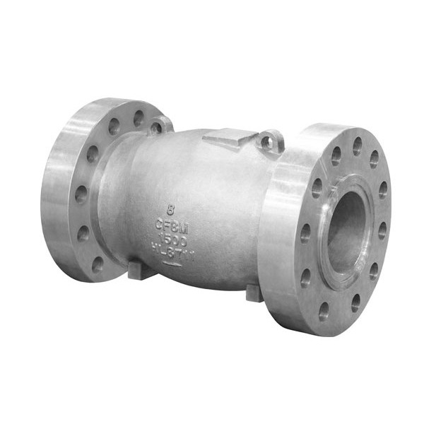
Industry nomenclature varies widely across different engineering disciplines. Engineers frequently specify these components as nozzle check valves or silent check valves. The internal body resembles a converging-diverging nozzle. This highly aerodynamic shape defines this specific industrial check valve class. The term "silent" refers to the complete elimination of the audible mechanical slam during pump shutdown.
Do not confuse these with basic inline spring checks used in residential plumbing. Industrial axial flow valves feature heavy-cast bodies, precision-machined diffusers, and engineered guide shafts designed for decades of continuous operation in severe environments.
The internal nozzle design streamlines fluid flow efficiently. It naturally centers the disc within the flow path. This symmetry drastically reduces turbulence and prevents destructive vortex shedding. The fluid passes around the central disc housing smoothly. The annular flow area expands gradually behind the disc assembly.
This gradual expansion recovers static pressure highly efficiently. It minimizes the overall pressure drop across the valve body. Compared to dual-plate or swing designs, the axial flow geometry provides a significantly higher flow coefficient (Cv). This efficiency reduces the energy required by the pumps to move the fluid through the system.
The central guide shaft keeps the disc perfectly aligned. Traditional valves suffer from uneven wear because the disc wobbles in the flow stream. The axial design supports the disc at both the front and rear of the shaft. This dual-point support eliminates lateral movement, ensuring the disc seats perfectly concentric every single time.
Compare the physical stroke length of different valve types. A swing check disc travels a long angular arc to close. An axial flow check valve features an ultra-short linear stroke. The disc moves only a fraction of the total pipe diameter. This minimal travel distance is a critical design feature.
For example, a 12-inch swing check valve requires the disc to travel several inches along an arc. A 12-inch axial flow valve disc might only travel one inch linearly. This short stroke translates directly to microsecond closure times. The spring pushes the lightweight disc over a very short distance instantly. This rapid response makes it the optimal choice for critical pump discharge applications. The valve reacts faster than the fluid column can reverse direction.
Specific industrial scenarios make axial flow designs non-negotiable. High-head pump stations face massive reverse flow potential due to gravity. When a pump pushes water up a steep elevation, a power failure causes the entire fluid column to reverse almost instantly. Multi-pump parallel systems experience complex surge interactions when a single pump trips offline while the others continue running.
Rapid-shutdown environments demand immediate, failsafe closure to protect the facility. Critical industry applications rely heavily on this technology. Desalination plants handle high-pressure, corrosive seawater that destroys standard valves. Oil and gas pipelines transport hazardous fluids over long distances, where a rupture causes environmental disaster. Complex municipal water infrastructure requires reliable surge protection to prevent catastrophic water main breaks in populated areas.
Flow conditions dictate the sizing process entirely. You must calculate the minimum flow required to fully open the valve. A partially open valve flutters continuously in the flow stream. This chattering causes premature wear on the internal guides and spring mechanisms. Engineers must verify the minimum, normal, and maximum flow rates before specification.
Engineers balance low pressure drop requirements with adequate spring tension. A weaker spring reduces the pressure drop but slows the closure time. A stiffer spring guarantees non-slam performance but increases the energy required to keep the valve open. Valve manufacturers calibrate this balance based on the exact fluid density and velocity profile.
We use the cracking pressure metric to determine when the valve begins to open. However, the fully open pressure is the critical metric. The system must generate enough velocity pressure to compress the spring completely and push the disc against the internal stop. If the disc floats between the seat and the stop, it will vibrate itself to pieces.
Internal component materials must match the fluid media. Corrosive or abrasive industrial fluids require specialized alloys. Springs manufactured from Inconel or Hastelloy resist chemical attack and maintain tension over millions of cycles. Standard stainless steel springs often suffer from chloride stress corrosion cracking in seawater applications.
The disc and seat materials must withstand the specific operating environment without degrading. Evaluate the trade-offs between seating materials carefully. Metal-to-metal seating provides durability for extreme temperatures and abrasive slurries. We specify Stellite overlays on the seating surfaces for high-wear applications. However, metal seating allows a small acceptable leakage rate under API 598 standards.
Resilient seating utilizes elastomers like EPDM, NBR, or PTFE inserts. This provides bubble-tight shutoff but restricts the maximum operating temperature of the valve. You must also ensure the elastomer is chemically compatible with the fluid. EPDM works perfectly for water but degrades rapidly in hydrocarbon applications.
Fluid Media | Recommended Body Material | Recommended Trim/Spring | Seating Type |
|---|---|---|---|
Treated Municipal Water | Ductile Iron / Carbon Steel | 316 Stainless Steel | EPDM Resilient |
Raw Seawater (Desalination) | Duplex Stainless Steel | Inconel 625 | Metal-to-Metal or PTFE |
Hydrocarbons / Oil | Carbon Steel (WCB) | 316 SS / Hastelloy | NBR or Metal-to-Metal |
High-Temp Boiler Feed | Chrome-Moly Steel | Inconel 718 | Stellite Overlay (Metal) |
System design philosophy often debates component-level mitigation. Ideal piping systems avoid transient surges inherently through smart design. Engineers use strategic pipe routing, large surge vessels, and variable frequency drives (VFDs) to control fluid momentum. These systemic solutions address the root cause of water hammer by slowly ramping down pump speeds.
However, spatial constraints and retrofit realities often eliminate these ideal options. Underground pump stations lack the physical space for massive surge tanks. Upgrading to VFDs requires significant electrical infrastructure changes and climate-controlled motor control centers. In these practical scenarios, installing a non-slam valve serves as the most effective and realistic primary defense against surge events.
You also have to consider the reliability of active systems. VFDs and motorized control valves require continuous electrical power and PLC signals to operate. During a total facility blackout, these active systems fail. A spring-operated check valve provides passive, mechanical protection that works regardless of power availability.
Engineered axial flow designs carry a higher initial procurement cost than standard swing checks. They also require longer lead times due to custom spring calibration and specialized manufacturing processes. Project managers must account for these upfront factors during the procurement phase. You cannot simply pull a 24-inch axial flow valve off a local distributor's shelf.
The financial justification comes from operational expenditure reductions. These valves extend pump lifecycles by preventing reverse rotation. They reduce pipeline maintenance by eliminating fatigue-inducing vibrations. Furthermore, their implementation often allows engineers to eliminate expensive secondary surge mitigation equipment. Removing a hydro-pneumatic surge tank from the design saves massive amounts of money in pressure vessel inspections and compressor maintenance.
Maintenance crews appreciate the axial design because it requires virtually zero intervention. Unlike swing checks that need frequent hinge pin replacements and cover gasket swaps, a properly sized axial valve operates for decades untouched. The internal guide bearings utilize the fluid media for lubrication.
Transient modeling prevents catastrophic sizing errors. Line-sizing is a dangerous but common industry practice. Matching the valve size directly to the pipe size often results in an oversized valve. The actual flow velocity fails to compress the spring fully. This leads to severe chattering and rapid mechanical failure.
You must size the valve based on actual volumetric flow rates. Incorporate these valves into hydraulic modeling software like Bentley WaterGEMS or AFT Impulse. Industry-standard practice assumes a zero closure delay for properly sized non-slam valves during the simulation. This assumption relies on accurate spring calibration.
Partner directly with valve manufacturers to mitigate sizing risks. Provide them with your system's specific deceleration rates and transient analysis data. They will perform custom spring tension calibration to ensure the valve matches your exact hydraulic profile perfectly. We always request a flow vs. pressure drop curve from the manufacturer to verify the valve will reach the fully open position under normal operating conditions.
Installers must provide a minimum of three to five pipe diameters (3D to 5D) of straight pipe upstream of the valve. This straight run conditions the flow profile, preventing turbulent eddies from unevenly loading the disc. Uneven loading causes the central shaft to bind, which completely negates the rapid-response design.
Conduct a comprehensive transient surge analysis on your current piping system to identify high-risk zones and calculate exact fluid deceleration rates.
Verify minimum, normal, and maximum volumetric flow rates to ensure accurate, flow-based valve sizing rather than relying on line-sizing.
Consult a specialized valve engineer to calibrate the internal spring tension specifically for your hydraulic profile.
Inspect existing swing check valves for signs of hinge pin wear, chattering, or audible acoustic slamming during pump shutdown.
A: A non-slam valve utilizes an engineered internal spring to actively push the disc closed as forward flow decelerates. It fully seats at the exact moment fluid velocity reaches zero, preventing reverse flow from initiating and eliminating the acoustic shockwave.
A: It prevents water hammer through an ultra-short disc stroke and precise spring tension. This allows the valve to close in microseconds, matching the fluid's deceleration rate and stopping reverse flow before it can generate a pressure surge.
A: Yes. Because the closure mechanism relies on spring tension rather than gravity, these valves operate effectively in horizontal, vertical upward, and vertical downward piping configurations without losing performance.
A: These terms generally describe the same technology. "Axial flow" refers to the straight-line fluid path. "Nozzle" describes the aerodynamic internal body shape. "Silent" refers to the operational result of eliminating the mechanical slam.
A: In software like Bentley WaterGEMS, engineers typically model true non-slam valves with a closure delay of zero. This assumes the valve is properly sized and the spring is calibrated to close exactly at zero velocity.
A: Chattering occurs when a valve is oversized for the actual flow rate, preventing the disc from fully opening. Fix this by replacing the valve with a smaller, flow-sized unit or installing a weaker spring calibrated to your specific flow conditions.


