


Views: 0 Author: Site Editor Publish Time: 2026-07-21 Origin: Site


Handling abrasive slurries and fibrous wastewater presents a severe operational challenge. Standard valves often fail in these harsh conditions. This failure causes disruptive downtime and dangerous pipeline blockages. Standard ANSI gate valves trap solid particles in their bottom cavities. This trapped debris permanently prevents full closure. Over time, internal leaks and complete system shutdowns occur.
A knife gate valve offers a purpose-built solution. Designed to rigorous TAPPI standards, it features a sharpened gate edge. It easily slices through heavy solids and fibrous media. We will provide a transparent, engineering-focused evaluation framework in this guide. You will learn how to specify the exact right valve for your system. We will show you how to prevent premature seat wear. You will also discover how to maximize valve lifecycle and reliability in the most demanding industrial applications.
Knife gate valves are purpose-built for liquids containing heavy solids but will fail if used for throttling or pure dry bulk without fluid suspension.
Preventing seat wear requires matching the elastomer (Natural Rubber, EPDM, Viton) to the exact abrasion and chemical profile of the media.
Clogging is often a result of improper operational timing; closing the valve while the slurry is flowing utilizes a self-cleaning fluid velocity.
Selecting the right isolation valve requires understanding specific mechanical advantages. You must also respect inherent design limitations. Engineers often misapply standard valves in high-solid environments. This leads to catastrophic failure.
The primary advantage lies in the gate geometry. The sharpened, beveled edge cuts directly through pulp, thick sludge, and mining tailings. Standard valves attempt to crush media into a seating area. This crushing action eventually damages the seat. The beveled gate pushes solids aside and shears through fibrous mats. It ensures a tight seal even when handling heavily contaminated wastewater.
You must understand where these valves succeed and where they fail. Transparency prevents misapplication.
Pressure limitations: Most resilient-seated designs are optimized for low-to-medium pressure applications. We typically see maximum pressure ratings capped around 150 psi (10 bar). High-pressure systems require different structural approaches.
Media limitations: These valves require fluid suspension to function properly. They will jam if applied to pure dry powder or dry grain. Without liquid to lubricate the media, dry solids pack tightly into the gate guides.
Functional limitations: These are strictly on/off isolation valves. Using them for flow throttling causes rapid, destructive erosion. High-velocity fluids will destroy both the gate and the elastomer seat.
You must distinguish between standard designs and extreme-duty alternatives. Standard models work well for light wastewater and paper pulp. However, highly abrasive mining applications demand a heavy-duty slurry gate valve. Slurry versions feature hardened steel gates and heavy-duty deflection cones. They also utilize robust packing arrangements to handle aggressive, high-density abrasive flows.
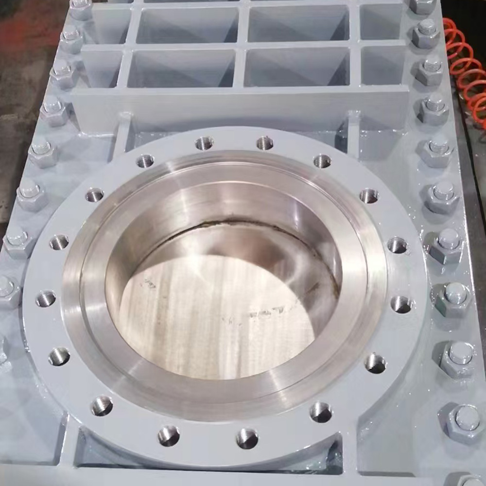
The top-works structure of your valve determines its environmental resilience. You must choose between bonnetless and bonneted configurations based on site conditions. Each design offers specific mechanical trade-offs.
Bonnetless models expose the upper gate and stem to the surrounding environment. They utilize an Outside Screw and Yoke (OS&Y) rising stem design.
Pros: They feature a lighter weight and a highly compact profile. Maintenance teams can easily perform visual inspections of the rising stem to confirm valve position.
Cons: They remain highly susceptible to environmental contamination. The inherent design tolerance allows for potential micro-leaks (weeping) at the packing gland. Airborne dust can also settle on the exposed stem.
Best for: General wastewater treatment and non-hazardous slurries. They excel in environments where minor external packing weeping remains manageable and safe.
Bonneted models enclose the entire gate within a sealed upper chamber. This structural change fundamentally alters how the valve interacts with the environment.
Pros: The fully enclosed gate prevents fugitive emissions completely. It protects internal mechanics from abrasive external dust and debris. This enclosure also handles higher system pressure spikes safely.
Cons: They require a significantly larger vertical footprint. They also add substantial installation weight to the pipeline infrastructure.
Best for: Hazardous chemical processing and pressurized sludge lines. They are mandatory in zero-tolerance leakage compliance environments.
Structural Feature | Bonnetless Design | Bonneted Design |
|---|---|---|
Gate Exposure | Exposed to ambient environment | Fully enclosed within a sealed chamber |
Fugitive Emissions | Prone to minor packing weeping | Zero-leakage compliance capability |
Weight & Profile | Lightweight, minimal vertical footprint | Heavyweight, tall vertical footprint |
Typical Application | Municipal wastewater, light pulp | Toxic chemicals, high-pressure sludge |
Mechanical design only solves half the equation. You must combine proper installation orientation with correct operational timing to prevent jamming. Clogging frequently occurs due to easily avoidable operator errors.
Sealing mechanics dictate how you must orient the valve during installation. Incorrect orientation guarantees internal leakage.
Uni-directional sealing: You must install the valve so system pressure pushes the gate into the seat. This forward pressure creates the mechanical seal. Reversing pressure on a uni-directional valve pushes the gate away from the seat. This causes catastrophic leakage and severe gate deflection.
Bi-directional sealing: These valves utilize specialized perimeter-sealing elastomers. They accommodate reverse flow safely. You should specify bi-directional models for complex slurry routing networks where flow directions change.
Operators commonly cause clogging by closing valves after shutting down pumps. You should implement a "dynamic closing" methodology instead.
Keep the primary slurry pump running at normal operational speeds.
Initiate the valve closure sequence while the fluid continues moving.
Allow the high fluid velocity to flush out bottom sediments. This acts like a pressure washer inside the pipeline.
Complete the closure just as the final solids wash away from the seating area.
Valve packing compresses and wears down through normal cycling. An adjustable knife gate valve allows operators to combat this wear actively. Maintenance teams must periodically tighten the packing gland to compensate for packing compression over time. You must balance this adjustment carefully. A tight seal prevents weeping, but excess friction causes actuator stalling. Regular, incremental adjustments prevent severe leaks while preserving smooth gate actuation.
Elastomer degradation causes most premature valve failures. Specifying the correct seat material extends valve life dramatically. You must analyze both the abrasive nature and the chemical makeup of your media.
Different compounds react differently to physical abrasion and chemical attack. Use the following chart to match elastomers to your process.
Elastomer Material | Abrasion Resistance | Chemical/Heat Tolerance | Ideal Applications |
|---|---|---|---|
Natural Rubber | Exceptional | Poor chemical resistance, low heat | Mining tailings, abrasive mineral slurries |
EPDM | Moderate | Good chemical resistance (up to ~120°C) | General wastewater, weak acid solutions |
Nitrile (Buna-N) | Good | Excellent oil and hydrocarbon tolerance | Hydrocarbon-laced sludges, oily wastewater |
Viton (FKM) | Good | Premium chemical resistance, high heat | Corrosive chemical slurries, hot acids |
Based on extensive field experience, you should set maintenance schedules according to application severity. Unrealistic expectations lead to unexpected pipeline failures.
Light duty: Systems handling raw water or light paper pulp typically see 120–240 months of service.
Medium duty: Applications managing abrasive mineral slurries usually require seat replacement every 30–60 months.
Severe duty: Harsh environments, such as pneumatic fly ash or high-velocity sand transport, destroy seats in just 6–12 months.
You must monitor valves for early warning signs of failure. "Passing" refers to internal leakage due to eroded seats. It indicates that high-velocity flow has washed away the elastomer. Torque anomalies represent another severe failure mode. If manual operators use cheater bars to force a jammed gate, they bend the stem. A bent stem drastically increases operational torque and eventually prevents the valve from moving.
Procurement involves more than selecting a valve body. You must size actuators correctly and ensure regulatory compliance. Overlooking these peripheral components leads to immediate operational bottlenecks.
Never undersize your pneumatic or electric actuators. Thick sludge and heavy slurries generate massive static friction against the gate. Applications require significant breakaway thrust to shear through compacted solids. If you size the actuator based purely on clean water calculations, it will stall during its first cycle in viscous mud.
You must select the correct pipeline connection geometry based on maintenance access requirements.
Wafer Style: This space-saving design sandwiches tightly between two pipeline flanges. It minimizes the face-to-face footprint. However, you cannot remove downstream piping without draining the entire system.
Lug Style: This design features threaded inserts covering the valve perimeter. It allows for end-of-line service. You can remove downstream piping safely while the valve holds back upstream pressure.
Municipal wastewater buyers must navigate strict legal frameworks. You must verify compliance when shortlisting manufacturers. Look for AIS (American Iron and Steel) certification for federally funded projects. Additionally, confirm BABA (Build America, Buy America) compliance. Failing to secure these certifications can force costly project redesigns or result in failed inspections.
Avoiding clogging and premature seat wear requires deliberate engineering choices. You must specify the correct elastomer seat material to handle specific chemical and abrasive loads. You must also respect inherent pressure limits and maintain proper packing tension over time. We highly recommend a proactive approach to your next installation.
Encourage your engineering and procurement teams to map out exact media viscosity before specifying equipment. Verify your process flow direction and document your maximum pressure constraints. Once you define these parameters, you can confidently request vendor quotes or CAD models. Taking these steps ensures a reliable, leak-free operation in your most demanding slurry environments.
A: No. High-velocity slurry will quickly erode the bottom of the gate and destroy the elastomer seat. They are strictly isolation (on/off) valves.
A: It is likely installed backward. Uni-directional valves rely on upstream line pressure to press the gate firmly against the downstream seat. Reversing this flow pulls the gate away, causing leaks.
A: It depends on cycle frequency and media abrasiveness. Initial adjustment is often required shortly after startup. You should follow this with regular visual inspections for weeping as part of routine preventative maintenance.


